Maintenance3303−5/A2
Winterthur Gas & Diesel Ltd.
4/ 5
3. Installation
1) Make sure that the bearing cover is clean and has no damage.
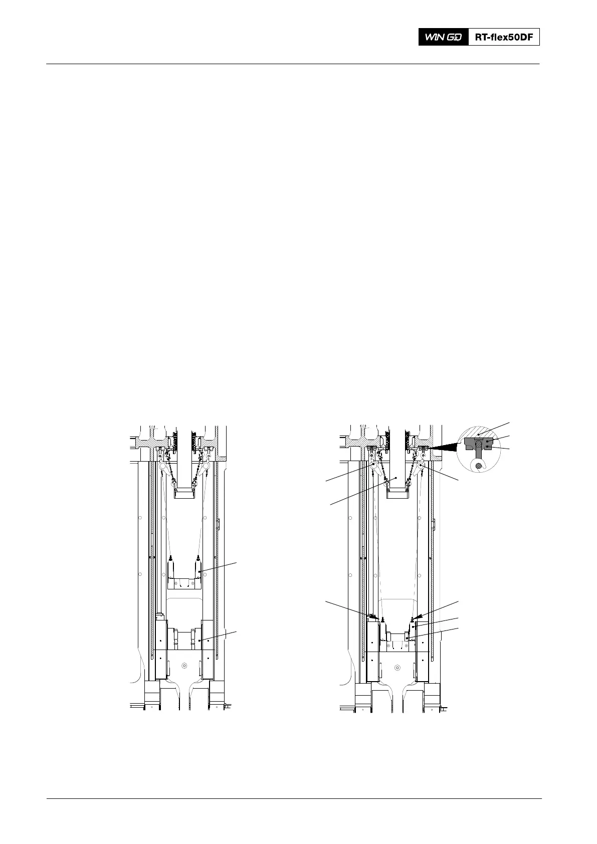
2) Attach the chain (94666I) to the eye bolts (EB1 and EB2) and the chain
block (H4) see Fig. 4 and Fig. 5.
3) Operate the chain block (H4) to lift the bearing cover.
4) Attach the manual ratchet (H3) to the chain (94666I).
5) Operate the chain block (H4) and the manual ratchet (H3) to move the bearing
cover into the column.
6) Remove the chain block (H4) from the chain 94666I).
7) Operate the manual ratchet (H3) to move the bearing cover above the crosshead
pin.
8) Attach the manual ratchets (H1, H2, Fig. 6) to the eye bolts (EB1, EB2).
9) Remove the manual ratchet (H3) from the chain (94666I).
10) Remove the chain (94666I) from the eye bolts (EB1, EB2).
Note: During step 11), make sure that the bearing cover (3) is level and
vertically aligned with the center of the crosshead pin (4). This prevents
damage to the elastic studs.
11) Operate carefully the manual ratchets (H1, H2) to lower the bearing cover (3) on
to the crosshead pin (4).
013.038/05
Fig. 6
EB2
H2H1
9433
1
2
3
4
EB1
013.038/05
5
4
3
Top End Bearing − Bearing Cover Removal and Installation
2016