Maintenance5552−1/A1
Winterthur Gas & Diesel Ltd.
4/ 5
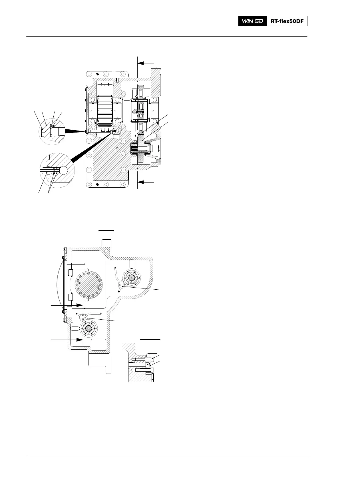
4. Nozzles
4.1 Removal
Note: To remove the nozzle (9, Fig. 5)
you must first remove the
applicable servo oil pump and
pinion.
Note: The nozzle (4) can be removed
easily after removal of cover (6).
1) Remove the two Allen screws (10) and
the cover (11).
2) Remove the nozzle (9).
3) Remove the the 10 screws (5).
4) Remove the cover (6) and its gasket.
5) Make sure that the gasket is
serviceable. Replace the gasket if
necessary.
6) Remove the nozzle (4).
7) Remove and discard the two
O-rings (3).
4.2 Installation
1) Clean the nozzles (9, 4).
2) Put the nozzle (9) in position.
3) Apply Loctite No. 243 to the threads of
the two Allen screws (10).
4) Attach the cover (11) with the two Allen
screws (10).
5) Put two new O-rings (3) on the
nozzle (4).
6) Put the nozzle (4) in position. Make
sure that the pin (7) engages with the
hole in the casing.
7) Attach the cover (6) with the 10
screws(5).
2016
Supply Unit: Servo Oil Pump and Servo Oil Pump Drive Removal and Installation
Fig. 5
56 7 8
43
1
2
I
I
I - I
II - II
II
II
9
9
10
11