Maintenance5552−4/A1
Winterthur Gas & Diesel Ltd.
2/ 3
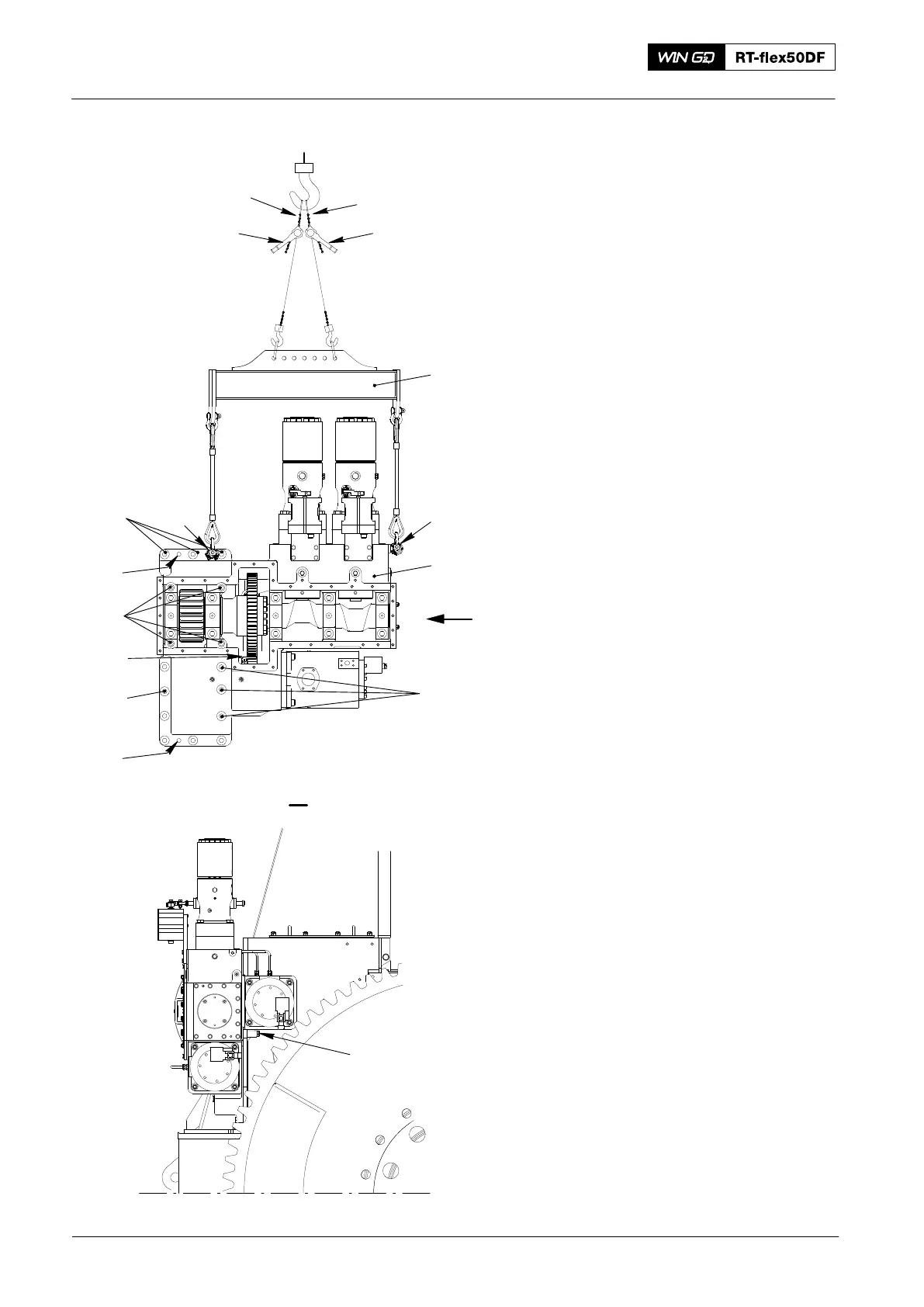
2. Removal
1) Remove the dowel pins (3, Fig. 2).
2) Remove the screws (7).
3) Attach the two chains (94202L) to the
engine room crane.
4) Attach the manual ratchets (H1, H2) to
the chains (94202L) and the lifting tool
(94557).
5) Attach the two eye bolts (EB) to
housing of the supply unit as shown.
6) Operate the engine room crane to
move the lifting tool above the eye bolts
(EB).
7) Attach the lifting tool (94557) to the two
eye bolts (EB).
8) Operate the manual ratchets (H1, H2)
to apply a light tension on the chains.
9) Remove the screws (8) together with
the distance sleeves.
10) Remove the screws (2, 4 and 6).
11) Operate carefully the engine room
crane to lift the supply unit from the
engine.
12) Move carefully the supply unit away
from the engine.
13) Lower the supply unit on to an
applicable surface.
2016
Removal and Fitting of Supply Unit
EB
1
EB
94557
H1
H2
2
7
3
6
5
4
3
013.043/05
94202L
94202L
013.042/05
Fig. 2
I
I
8