Maintenance
8752−1/A1
Winterthur Gas & Diesel Ltd.
5/ 6
18) Do a quality check of the sealing surface (SF). If necessary use new emery cloth
of the same grade and do step 3) to step 17) again.
19) Replace the emery cloth with a smoother grade, then do step 3) to step 17)
again.
20) Replace the emery cloth with a polishing cloth as a last step to polish the HP fuel
pipe.
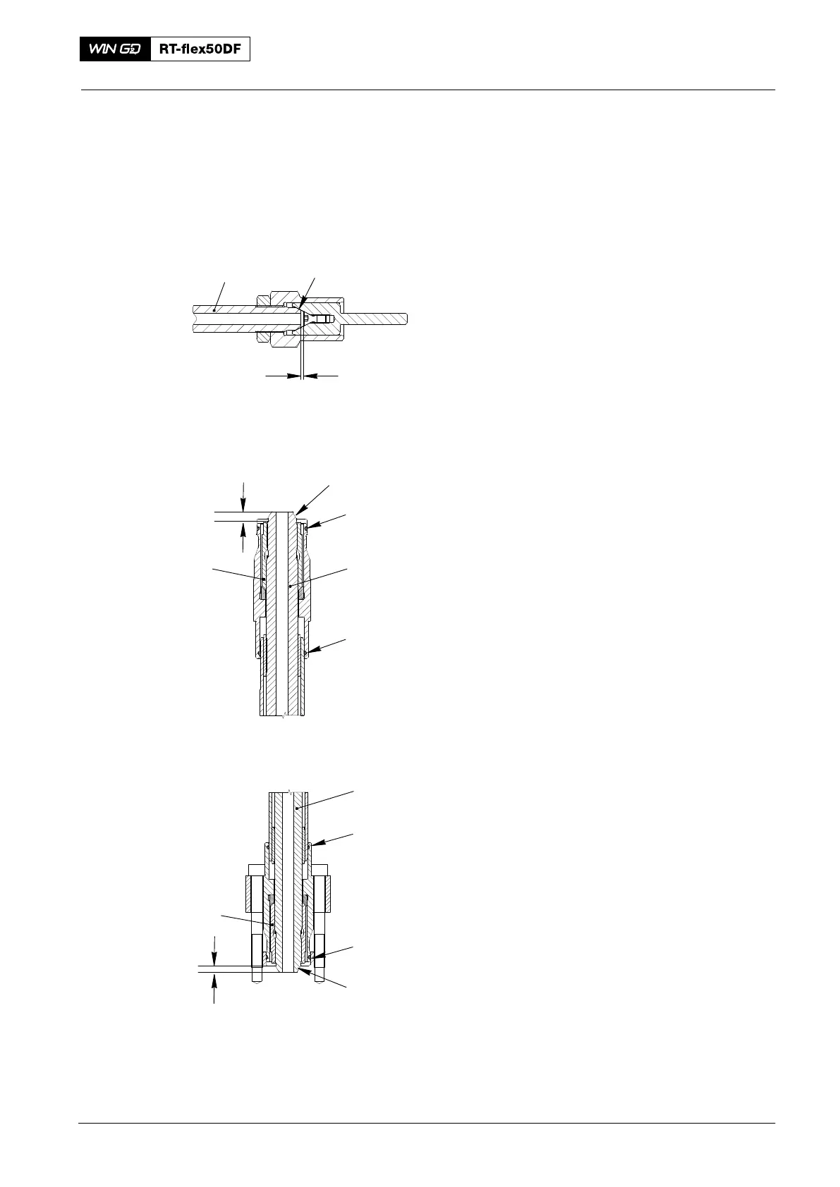
Note: If you find large notches, you must
make the HP fuel pipe (1, Fig. 5)
shorter. Make sure that there is a
minimum distance of 0.5 mm
between the countersunk screw
and the sealing face (SF) on the
HP fuel pipe.
21) Remove the screw-on sleeve (94870E,
Fig. 4).
22) Attach the claw (2) to the HP fuel
pipe (3).
4. Installation
1) Do a check for damage of the O-rings
(1 and 3, Fig. 6). If necessary, replace
the O-rings.
2) Remove all the protection from the
sealing faces (SF).
3) Make sure that the claw (4) is correctly
attached to the HP fuel pipe (2).
Note: You can adjust the claw (4) with an
open-ended wrench.
4) Make sure that there is a distance of
10.0 mm between the end of the HP
fuel pipe (2) and the claw (4).
5) Make sure that the O-rings (1, 3) are in
the correct position.
2016
HP Fuel Pipe: Removal, Grind, Installation
016.739/08
SF
1
Fig. 5
Minimum 0.5 mm
10.0 mm
1
3
SF
4
2
WCH02982
10.0 mm
WCH02982
5
SF
2
7
6
Fig. 6