Maintenance
1132−1/A1
Winterthur Gas & Diesel Ltd.
3/ 3
4. Waisted Studs − Apply Tension
After you install the main bearing cover (see 1132−2), apply tension to the waisted
studs (3) as follows:
1) Install the double pre-tensioning jacks (94114B) as given in paragraph 2.
2) Start the hydraulic unit (94942).
3) When oil that has no air flows out, close the vent screw (7, Fig. 3) on the
pre-tensioning jacks (94114B).
4) Operate the hydraulic unit (94942), to get a pressure of 1000 bar. Keep the
pressure constant.
5) Use the round bar (4) to tighten all the nuts (3).
Note: Make sure that there is no clearance between the main bearing girder (1,
Fig. 2) and the main bearing cover (2).
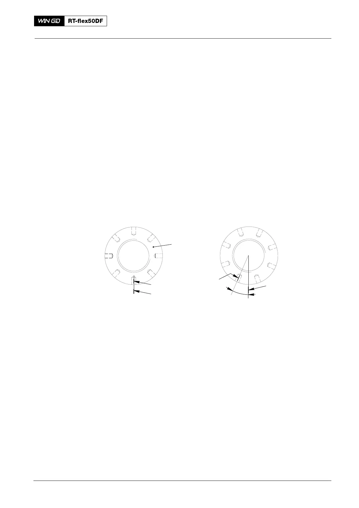
6) Mark the position of the nuts (1, Fig. 4) on the bearing cover (1
st
Step).
1
ST
STEP
2
ND
STEP
y
x
4
013.432/05
009.758/02
y
TIGHTENING
ANGLE
x
Fig. 4
7) On the hydraulic unit (94942), increase the pressure to 1500 bar. Keep the
pressure constant.
8) Use the round bar (4, Fig. 3) to tighten fully all the nuts (3). Use the feeler gauge
(94122) to do a clearance check through the slot (5).
9) On the hydraulic unit (94942), decrease the pressure to zero.
10) Remove the double pre-tensioning jacks (94114B).
Note: Make sure that all the nuts are turned approximately i.e. the tightening
angle must be 20° between the 1
st
Step and 2
nd
Step, see Fig. 4. If larger
differences occur, do step 1) to step 10) above again.
11) Use the special feeler gauge (94123) to do a check of the vertical clearance
(refer to 0330−1 Clearance Table, Crankshaft and Main Bearing’).
Note: All main bearing clearance values are applicable only with tightened tie
rods and waisted studs.
Main Bearing: Main Bearing: Waisted Studs − Loosen and Apply Tension
2016