HYDRAULIC SYSTEM
M8540Narrow, M9540Narrow, WSM
N8-S14
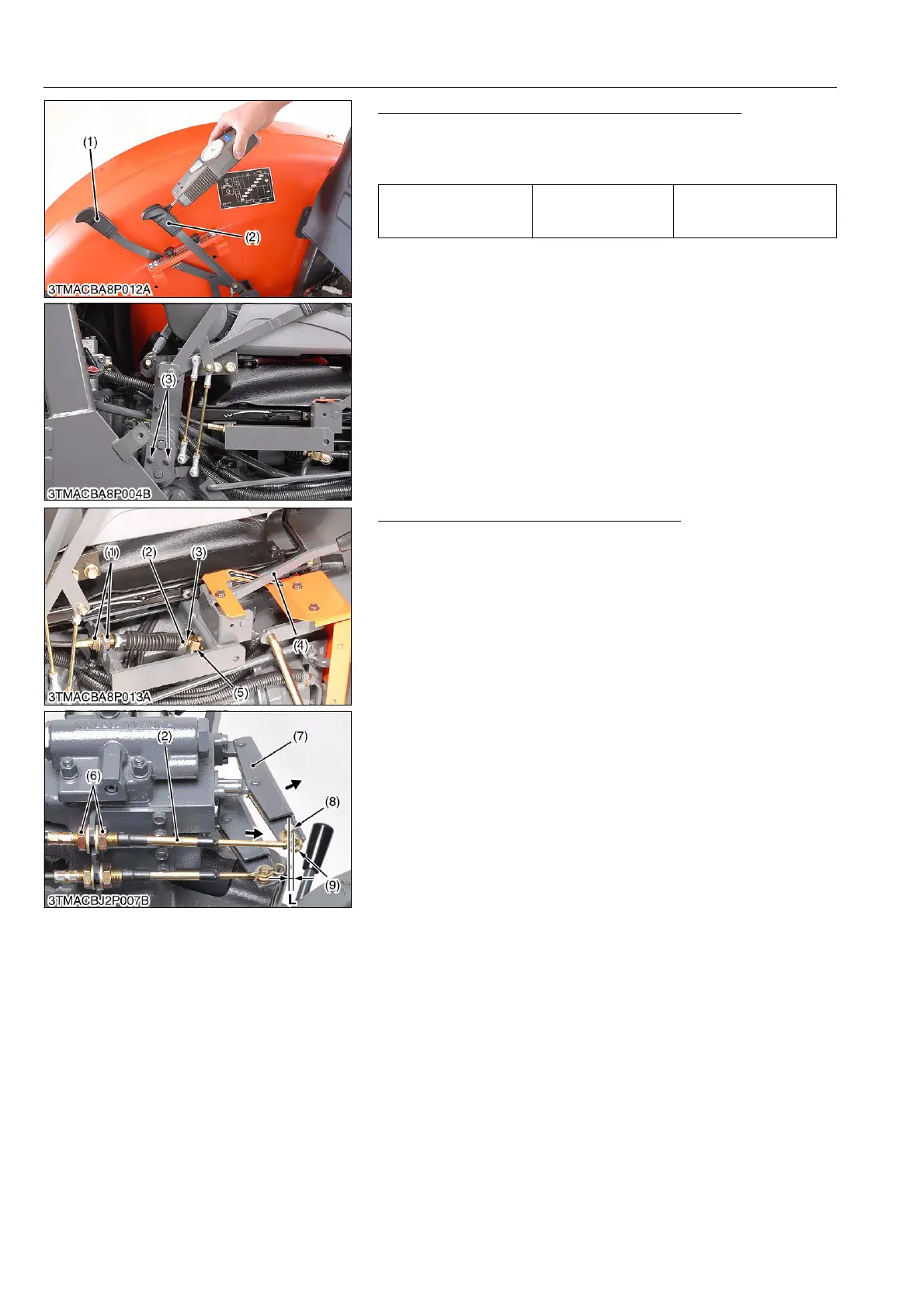
Position and Draft Control Lever Operating Force
1. Check the position and draft control lever operating force.
2. If measurement is not within the factory specification, adjust the
with tightening nuts (3).
9Y1210236HYS0012US0
Adjusting Wire of Auxiliary Control Valve
(Lever Side)
1. Screw in the wire (2) to the rod end (5) fully.
2. Shift the control lever (4) forward and fix the wire with lock nuts
(3) to contact the control lever (4) and stopper.
3. Fix the wire (2) with retaining nut (1) center of thread.
(Valve Side)
1. Pull the auxiliary valve lever (7) to a full engage position.
2. Pull out the wire (2) fully, and fix the wire with retaining nuts (6)
to be a length "L" between wire end (9) and valve lever pin (8)
as shown photo.
9Y1210236HYS0013US0
Operating force for
position and draft control
lever
Factory specification
20 to 40 N
2.0 to 4.1 kgf
4.5 to 9.0 lbf
(1) Position Control Lever
(2) Draft Control Lever
(3) Nut
(1) Retaining Nut (Lever Side)
(2) Wire
(3) Lock Nut
(4) Control Lever
(5) Rod End
(6) Retaining Nut (Valve Side)
(7) Auxiliary Valve Lever
(8) Lever Pin
(9) Wire End
L: 0 to 3.0 mm (0 to 0.118 in.)
 Loading...