HYDRAULIC SYSTEM
M8540Narrow, M9540Narrow, WSM
N8-S20
(2) M9540Narrow Cabin Model
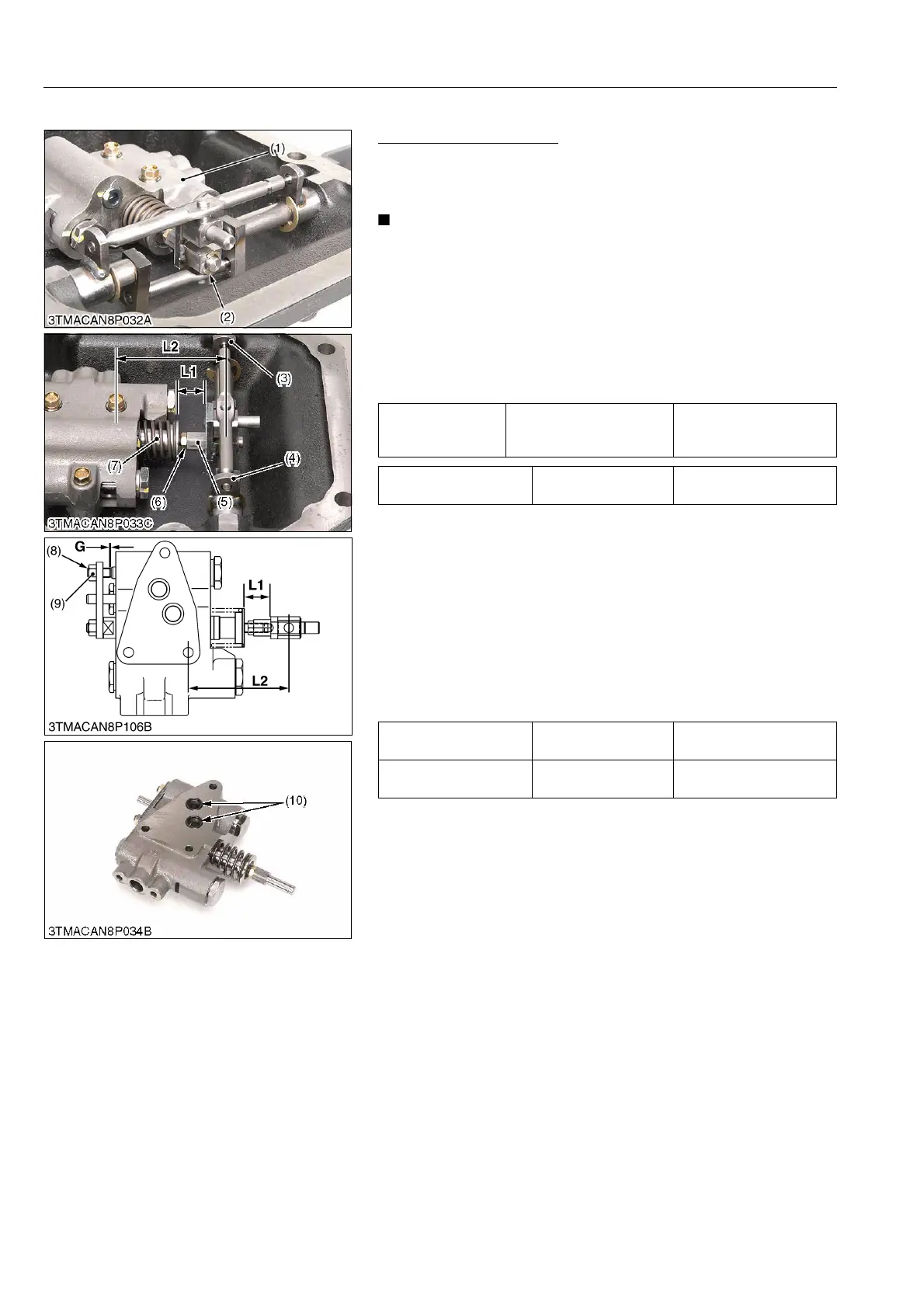
Removing Control Valve
1. Remove the E-shaped stopper (2).
2. Remove the control valve mounting screws.
3. Remove the control valve (1).
• Do not disassemble the spool joint 1 (5) from the spool (7)
unless necessary.
If disassembled due to unavoidable reasons, record the
installation length (L1) between the spool joint 3 and spring
retainer. (as shown figure.)
When reassembling, be sure to make a former length.
• Do not loosen the adjusting screw (8) unless necessary.
(When reassembling)
• Be sure to fit the O-rings (10).
Q Adjusting Spool Joint
1. Set the length "L1" to the reference value or recorded value.
2. Set the length "L2" to the factory specification (neutral state),
with operate the draft feedback lever (4) and position link lever
(3).
3. Check the gap "G" between the lowering poppet and adjusting
screw (8).
4. If the gap "G" is not within the reference valve, recheck the
length "L2" at the neutral state of spool.
If necessary to adjust the gap "G", loosen the lock nut (9) and
adjust by the adjusting screw (8).
9Y1210236HYS0030US0
Tightening torque
Control valve mounting
screw
20 to 23 N·m
2.0 to 2.4 kgf·m
15 to 17 lbf·ft
Length "L1" Factory specification
24.5 to 25.0 mm
0.965 to 0.984 in.
Length "L2" Reference Value
66.3 to 66.7 mm
2.61 to 2.62 in.
Gap "G" Reference Value
0.2 to 0.3 mm
0.008 to 0.01 in.
(1) Control Valve
(2) E-shaped Stopper
(3) Position Link Lever
(4) Draft Link Lever
(5) Spool joint
(6) Lock Nut
(7) Spool
(8) Adjusting Screw
(9) Lock Nut
(10) O-ring
G: Gap