HYDRAULIC SYSTEM
M8540Narrow, M9540Narrow, WSM
N8-S15
4. DISASSEMBLING AND ASSEMBLING
[1] HYDRAULIC PUMP
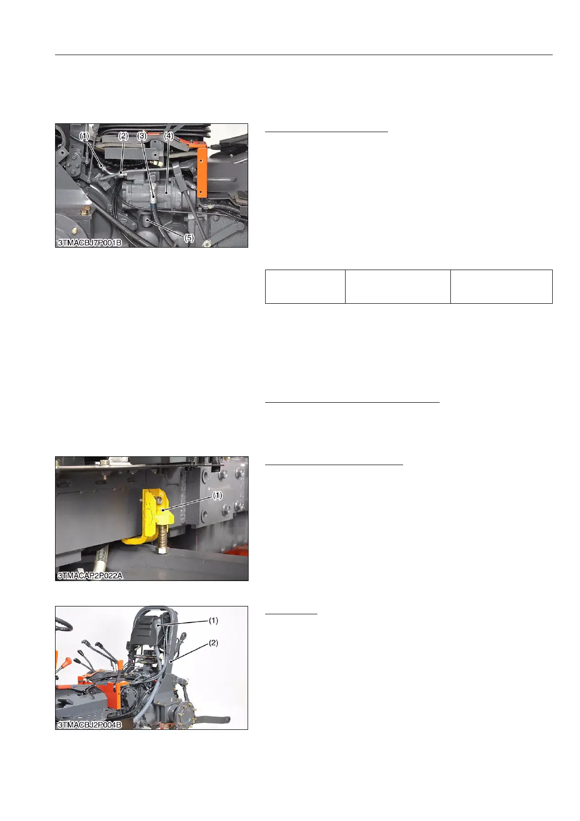
(1) Removing Hydraulic Pump
Hydraulic Pump Assembly
1. Place the disassembling stand under the transmission case.
2. Remove the right rear wheel and fender. (ROPS Model)
Remove the right rear wheel. (CABIN Model)
Remove the right crawler track and sprocket. (CRAWLER
Model)
3. Remove the differential lock rod (1).
4. Disconnect the power steering delivery pipe (2).
5. Disconnect the 3-point hitch delivery pipe (3).
6. Disconnect the suction pipe (5).
7. Remove the hydraulic pump (4).
(When reassembling)
9Y1210236HYS0014US0
[2] HYDRAULIC BLOCK
(1) Preparation
Draining Fuel and Transmission Fluid
1. Refer to "3. CHECK AND MAINTENANCE" and "2.
LUBRICANTS, FUEL AND COOLANT" at "NG. GENERAL"
section.
9Y1210236CLS0006US0
Front Axle Rocking Restrictor
1. Install the front axle rocking restrictor (1) (refer to "8. SPECIAL
TOOLS" at "NG. GENERAL" section) to the front axle bracket
on both sides.
9Y1210236HYS0016US0
(2) ROPS Model
Rear ROPS
1. Remove the rear ROPS (2) with upper fuel tank (1) refer to the
"2. DISASSEMBLING AND ASSEMBLING" at "N2. CLUTCH"
section.
9Y1210236HYS0017US0
Tightening torque Rear wheel mounting nut
260 to 304 N·m
26.5 to 31.0 kgf·m
191.8 to 224.2 lbf·ft
(1) Differential Lock Rod
(2) Power Steering Delivery Hose
(Pipe)
(3) 3-point Hitch Delivery Hose (Pipe)
(4) Hydraulic Pump
(5) Suction Pipe
(1) Front Axle Rocking Restrictor
(1) Upper Fuel Tank (2) Rear ROPS