ELECTRICAL SYSTEM
M8540Narrow, M9540Narrow, WSM
N9-S14
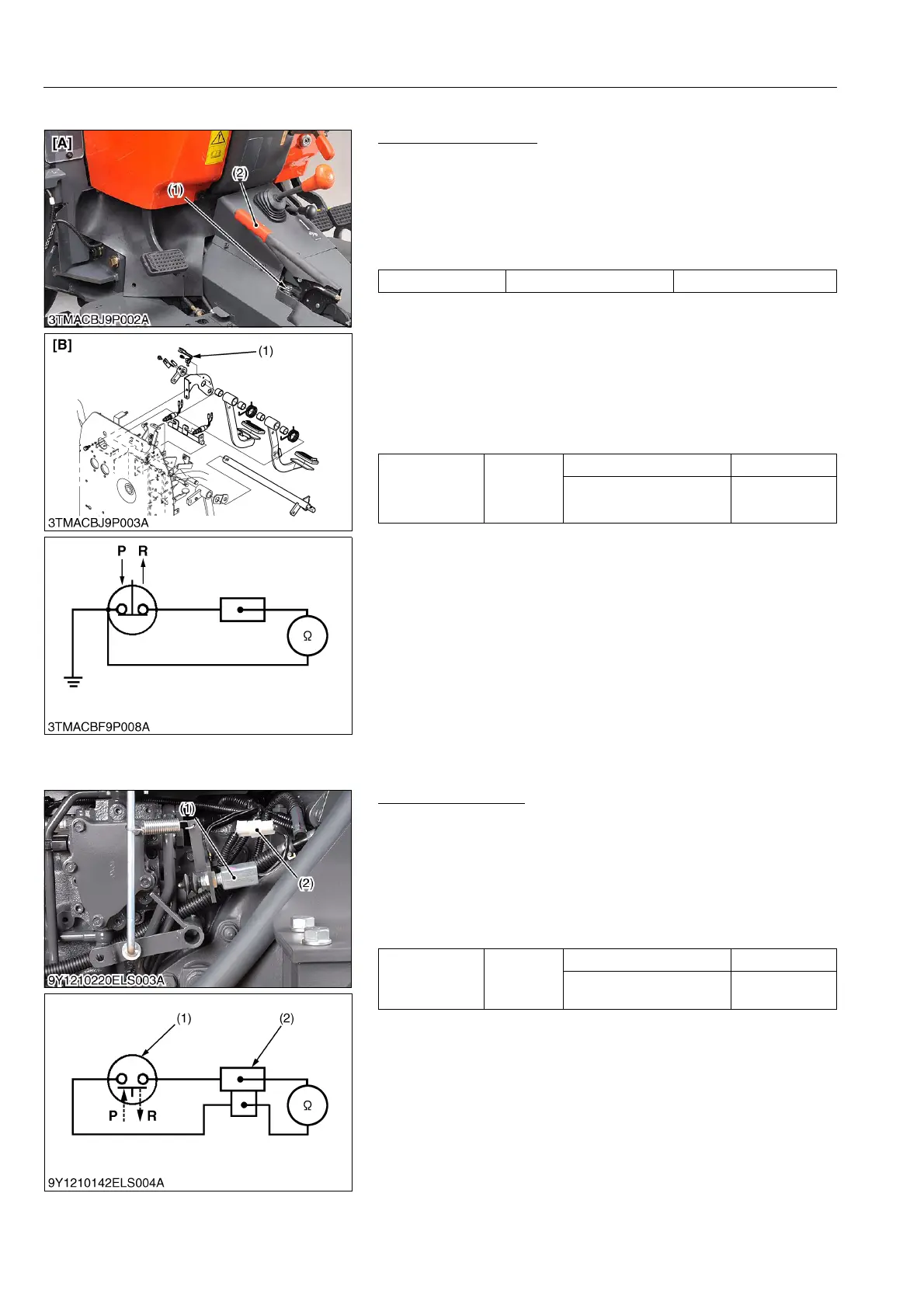
(2) Parking Brake Switch
Parking Brake Switch
1) Connector Voltage
1. Remove the connector.
2. Turn the main switch ON position.
3. Measure the voltage across the terminal and chassis.
4. If the voltage differs from battery voltage, the wiring harness,
fuse, or main switch is faulty.
2) Parking Brake Switch Continuity
1. Remove the parking brake switch (1).
2. Check the continuity with an ohmmeter across the switch
terminal and chassis.
3. If it does not conduct or any value is indicated when the switch
is released, the switch is faulty.
4. If infinity is not indicated when the switch is pushed, the switch
is faulty.
(When reassembling)
[CABIN Model Only]
• Turn on the parking brake indicator at instrument panel, when
parking brake lever operated one or two notches and more.
Be sure to not indicate the parking brake indictor when parking
brake lever at off position.
• Adjust the parking brake switch position.
9Y1210236ELS0018US0
(3) Ground PTO Switch
Ground PTO Switch
1) Ground PTO Switch Continuity
1. Check the continuity with an ohmmeter across the switch
connector (2).
2. If it does not conduct or any value is indicated when the switch
is pushed, the switch is faulty.
3. If infinity is not indicated when the switch is released, the switch
is faulty.
(When reassembling)
• Assemble the ground PTO switch (1) thread at the center.
9Y1210236ELS0026US0
Voltage Terminal – Chassis Approx. battery voltage
Resistance
(Across switch
terminal and
chassis)
Reference
value
When switch is pushed Infinity
When switch is released 0 Ω
(1) Parking Brake Switch
(2) Parking Brake Lever
[A] ROPS Model
[B] CABIN Model
P: Pushed
R: Released
Resistance
(Across switch
terminals)
Reference
value
When switch is pushed "P" 0 Ω
When switch is released
"R"
Infinity
(1) Ground PTO Switch
(2) Connector
P: Pushed
R: Released