ELECTRICAL SYSTEM
M8540Narrow, M9540Narrow, WSM
N9-S13
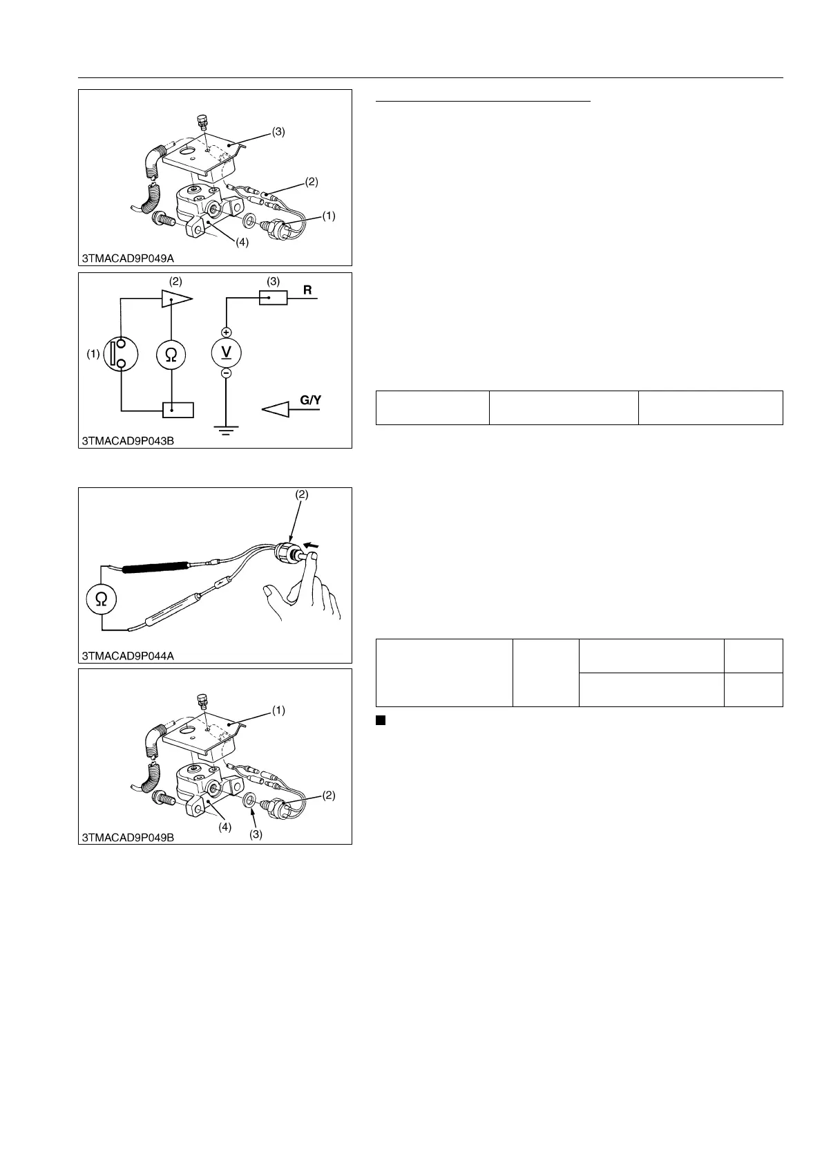
Turning Angle Inspection Switch
1. Remove the switch cover (3) from the left side front case
support (4).
2. Disconnect the turning angle inspection switch connector (2)
after turning the main switch off.
3. Perform the following checking 1) and 2).
9Y1210236ELS0015US0
1) Connector Voltage
1. Turn the main switch ON position.
2. Set the 4WD / Bi-speed turn switch to Bi-speed position.
3. Measure the voltage with a voltmeter across the wiring harness
connector B terminal and chassis.
4. If the voltage differs from the battery voltage (11 to 14 volts),
check the 4WD / Bi-speed turn switch or wiring harness.
9Y1210236ELS0016US0
2) Turning Angle Inspection Switch
1. Measure the resistance with an ohmmeter across the two 1P
connectors.
2. If infinity is not indicated, the turning angle inspection switch is
faulty.
3. Measure the resistance with an ohmmeter across the two 1P
connectors while pushing the push rod of switch.
4. If 0 ohm is not indicated, the turning angle inspection switch is
faulty.
• After reassembling the Bi-speed turn sensor, be sure to
check its operation.
1. When the front wheels are straight ahead, the resistance
value of the turn angle inspection switch is infinity.
2. When the turning angle exceeds approximately 0.57 rad
(32 °), the resistance value of the turning angle inspection
switch is 0 ohm.
If the resistance values specified above are not indicated,
adjust with the shim (3).
(Reference)
• Thickness of adjusting shim
0.5 mm (0.020 in.)
1.0 mm (0.039 in.)
9Y1210236ELS0017US0
(1) Turning Angle Inspection Switch
(2) Connector
(3) Switch Cover
(4) Front Case Support
Voltage
Connector B terminal –
Chassis
Battery voltage
(1) Turning Angle Inspection Switch
(2) 1P Connector (Switch Side)
(3) 1P Connector (Wiring Harness
Side)
Resistance across two
1P connectors
Factory
specifica-
tion
When the push rod is
normal position
Infinity
When the push rod is
pushed
0 ohm
(1) Switch Cover
(2) Turning Angle Inspection Switch
(3) Shim
(4) Front Case Support
 Loading...