HYDRAULIC SYSTEM
M8540Narrow, M9540Narrow, WSM
N8-S16
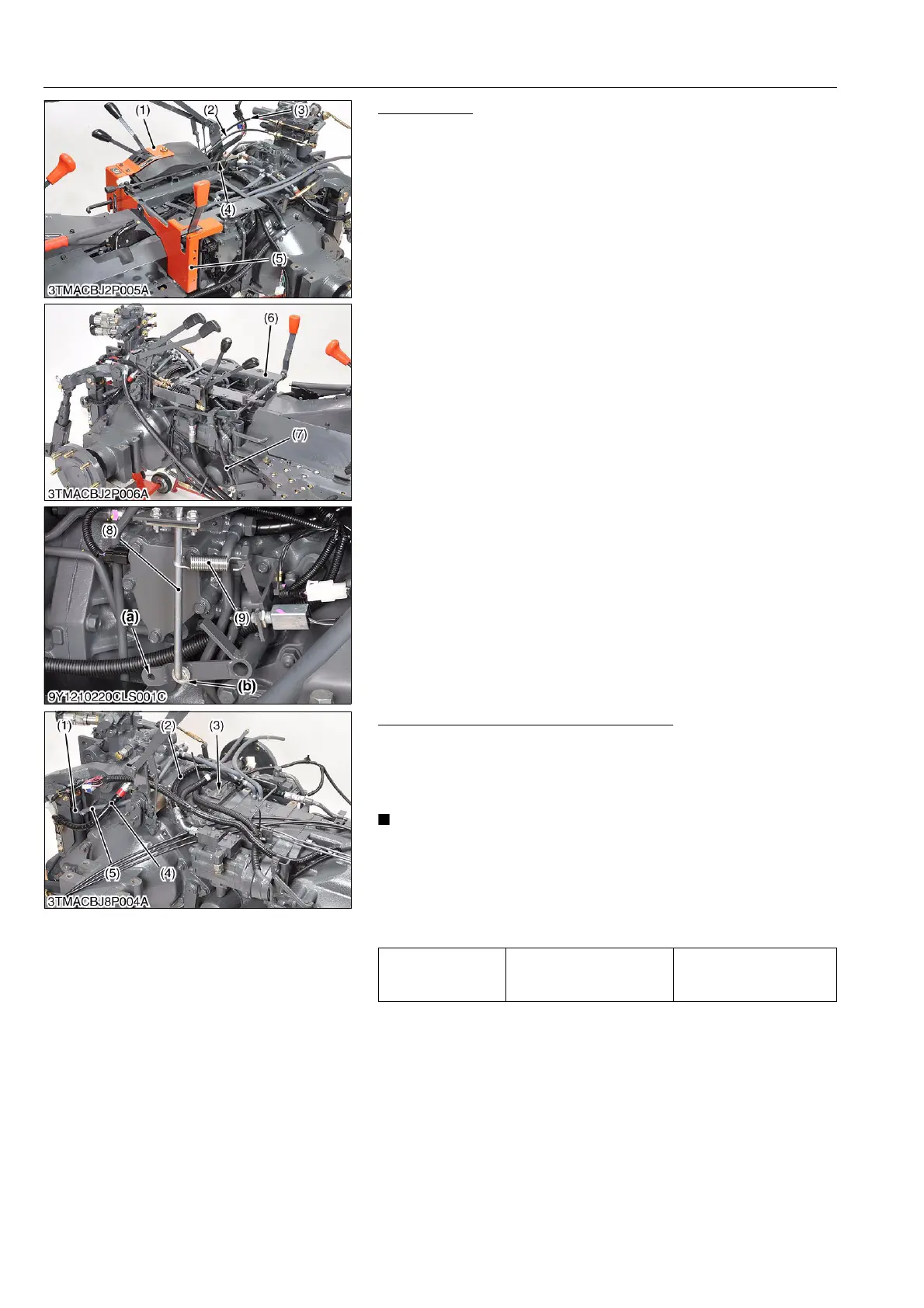
Seat Bracket
1. Remove the hydraulic remote valve wires (2) and (3).
2. Remove the lowering speed link rod (4).
3. Remove the remote control lever cover (1).
4. Remove the cover (5).
5. Remove the H-L shift rod (7).
6. Remove the ground PTO rod (8) and spring (9).
7. Remove the seat bracket (6).
(When reassembling)
• Adjust the remote valve wire. (Refer to the N2 section.)
• Be sure to assemble the ground PTO rod (8) to the hole (b).
9Y1210236HYS0018US0
Hydraulic Cylinder and Ground Harness
1. Remove the cylinder hoses (4) and return hoses (5).
2. Remove the cylinders (1).
3. Disconnect the ground harness (3).
4. Remove the hydraulic hose (2).
• Take care not to damage the grease nipple when remove
the hydraulic cylinder pin.
(When reassembling)
• Apply grease to the grease nipples.
• Take care not to damage the grease nipples when reassemble
the hydraulic cylinder.
9Y1210236HYS0019US0
(1) Remote Control Lever Cover
(2) Remote Valve Wire
(3) Remote Valve Wire
(4) Lowering Speed Link Rod
(5) Cover
(6) Seat Bracket
(7) H-L Shift Rod
(8) Ground PTO Rod
(9) Spring
(a) Hole for CABIN Model
(b) Hole for ROPS Model
Tightening torque Cylinder hose retaining nut
45.1 to 53.0 N·m
4.6 to 5.4 kgf·m
33.3 to 39.1 lbf·ft
(1) Cylinder
(2) Hydraulic Hose
(3) Ground Harness
(4) Cylinder Hose
(5) Return Hose
 Loading...