03/2003
4-31
8850/ 510DP
REP 8.2
Repairs and Adjustments
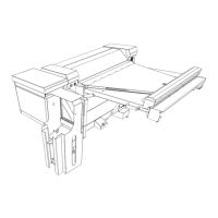
7. (Figure 4): Remove the Media Transport Module from the Printer.
Figure 4 Removing the Media Transport Module
Replacement
CAUTION
Ensure that the Top Cover and the Image Module of the Printer are in the raised position prior
to beginning this replacement procedure.
NOTE: In the following steps, the terms “Left” and “Right” describe machine locations as
observed from the Roll Media Supply Drawer side of the Printer.
1. Set the Media Transport Module back onto the floor plate of the printer.
2. (Figure 5): Align the right side of the Media Transport Module Shaft with the spring-loaded
Shaft Release Pin. Reinstall the Media Transport Module
Figure 5 Reinstalling the Media Transport Module
3. (Figure 3): Reattach the connectors on the left side of the Media Transport Module.
4. Reinstall the Fuser Drive Gear.
2
Disengage the shaft from the retaining
slot at the rear of Printer frame by pull-
ing this end of Media Transport
Assembly out first
3
Rotate the Media Transport Assembly as shown to
clear the assembly of its mounting hardware at
either end
4
Lift the Media Transport Assem-
bly out of the Printer and place
on a clean, flat surface
1
Ensure that the tension on the Shaft
Release Pin has been released (Fig-
ure 1)
Media Transport
Module Shaft
Shaft Release Pin
1
Align Media Transport Module
Shaft with spring-loaded Shaft
Release Pin
2
Press the Media Transport Module
Shaft into the Shaft Release Pin,
compressing it
3
As the Shaft Release Pin is compressed, swing the left side of the Media
Transport Module Shaft inward, and into the retaining slot in left side of the
Printer frame

 Loading...
