03/2003
4-59
8850/ 510DP
REP 9.2
Repairs and Adjustments
NOTE: The latches that secure the Xerographic Module to the Printer Frame are spring-
loaded and will automatically engage the holes in the frame when it is lifted upright. When
performing the following procedure, listen for the latches to engage.
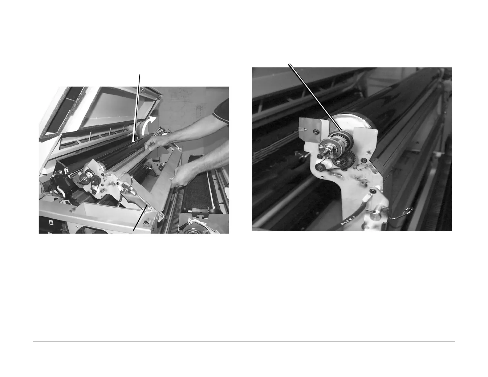
5. (Figure 4): Raise the Xerographic Module to the service position.
Figure 4 Elevating the Xerographic Module to Service Position
NOTE: In the following steps, the terms “Left” and “Right” describe machine locations as
observed from the Roll Media Supply Drawer side of the Printer.
6. (Figure 5): Loosen the Bearing Retainer from the left side of the Xerographic Module. (It is
a wire spring that goes over the top of the left Bearing.)
Figure 5 Loosen the Bearing Retainer
1
With the Xerographic Module lying hori-
zontally, slide it towards the manual
infeed area
2
Carefully raise the Xerographic Module
to the upright position
3
Listen for positive engagement of the latches
at the base of the brackets prior to releasing
the Xerographic Module
1
Push the Bearing Retainer inward to remove it from the bearing
 Loading...


