03/2003
4-140
8850/ 510DP
REP 14.1
Repairs and Adjustments
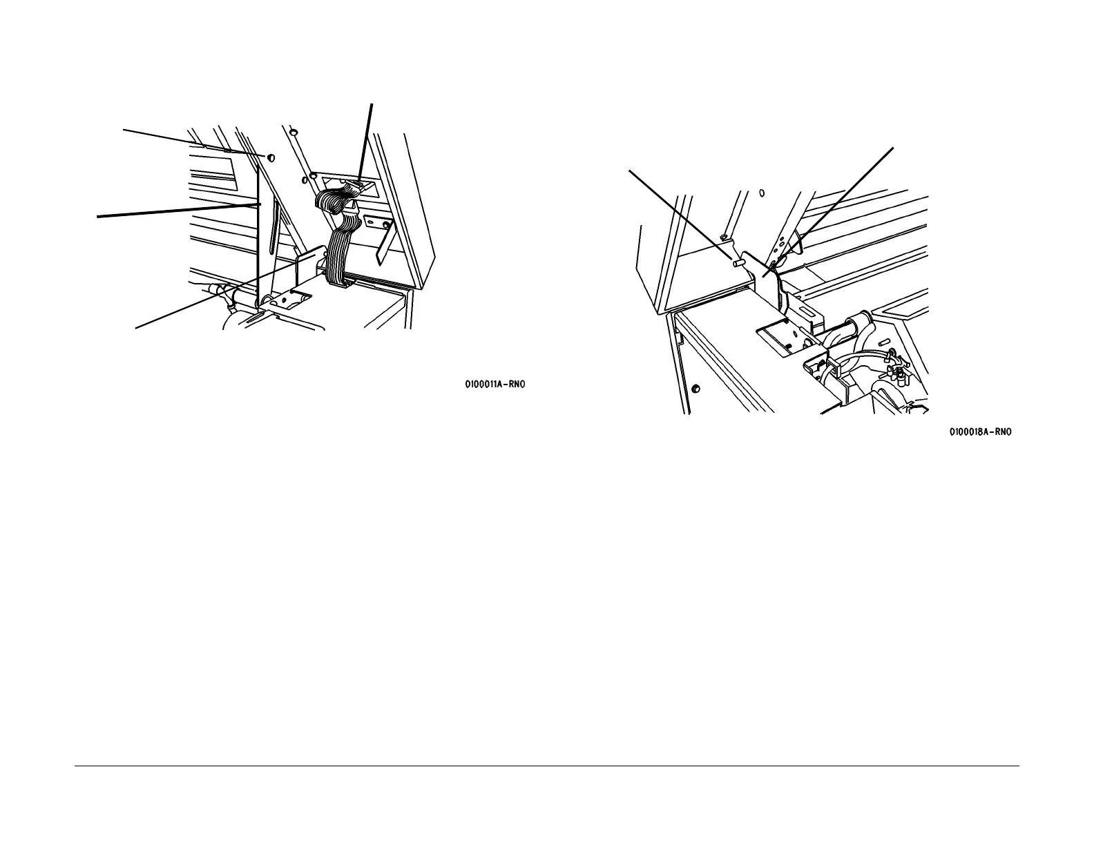
4. (Figure 3): Prepare to remove the Top Cover (Front).
Figure 3 Preparing to Remove the Top Cover (Front)
NOTE: (Figure 2): Observe the way that the Top Cover Pivot Pin engages the hole in the Inter-
lock Plate. This may be a difficult area during reassembly.
5. Open the Developer Module Cover, and remove the two pivot pins shown in Figure 3 and
Figure 4.
Figure 4 Top Cover Interlock Plate
6. Close the Developer Module Cover and lift off the Top Cover, being careful to disengage
the small pin from the Interlock Plate.
Top Cover Pivot Pin
(will be removed in
Step 4)
2
Support the Cover
then remove the
Pin
1
(8850Disconnect
A32/P1
3
Lower the Latch
Plate then lower
the cover to the
closed position
interlock Plate
Top Cover Pivot Pin
 Loading...


