10-7
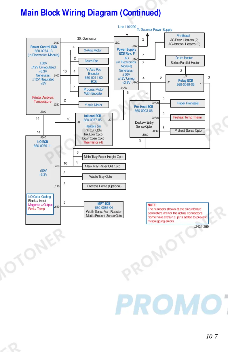
Main Block Wiring Diagram (Continued)
Inkload ECB
660-0077-05
Heaters (4)
Ink Out Opto
Ink Low Opto
Door Open Opto
Thermistor (4)
Process Motor
With Encoder
Y-axis Motor
Drum Fan
X-Axis Motor
Power Supply
ECB Rev. F
AC
(in Electronics
Module)
Generates:
±50V
±12V Unreg
+3.3V
Printhead
AC Resv. Heaters (2)
AC Jetstack Heaters (2)
Drum Heater
Series/Parallel Heater
Pre-Heat ECB
660-0003-06
4
10
5
2
2
4
4
4
7
3
MPT ECB
660-0086-04
Width Sense Var. Resistor
Media Present Sense Opto
30, Connector
Y-Axis Pos
Encoder
660-0011-00
ECB
Deskew Entry
Sense Opto
Waste Tray Opto
Main Tray Paper Height Opto
Main Tray Paper Out Opto
Process Home (Optional)
5
2
10
3
16
7
3
3
3
NOTE:
The numbers shown at the circuitboard
perimeters are for the actual connectors.
Some have extra n.c. pins added to prevent
misplugging errors.
3
Preheat Sense Opto
2
3
2
Paper Preheater
Preheat Temp Therm
5
Relay ECB
660-0019-03
To Scanner Power Supply
3
I/O ECB
660-0079-11
Power Control ECB
660-0074-13
(in Electronics Module)
±50V
±12V Unregulated
+3.3V
Generates:
±12V Regulated
+5V
Printer Ambient
Temperature
I/O Color Coding
Black = Input
Magenta = Output
Red = Temp
14
14
+50V
+3.3V
s2424-25
J480 JDC1
J3AC
J2AC
J4AC
J1AC
J400
J280
J800
J840
J860
J0660
J0760
J0720
J400
J1
J2
J2
J3
J1
J110
J610
 Loading...