4.5 I/O Signal Connections
4.5.4 I/O Circuits
4-39
4
Wiring and Connecting SERVOPACKs
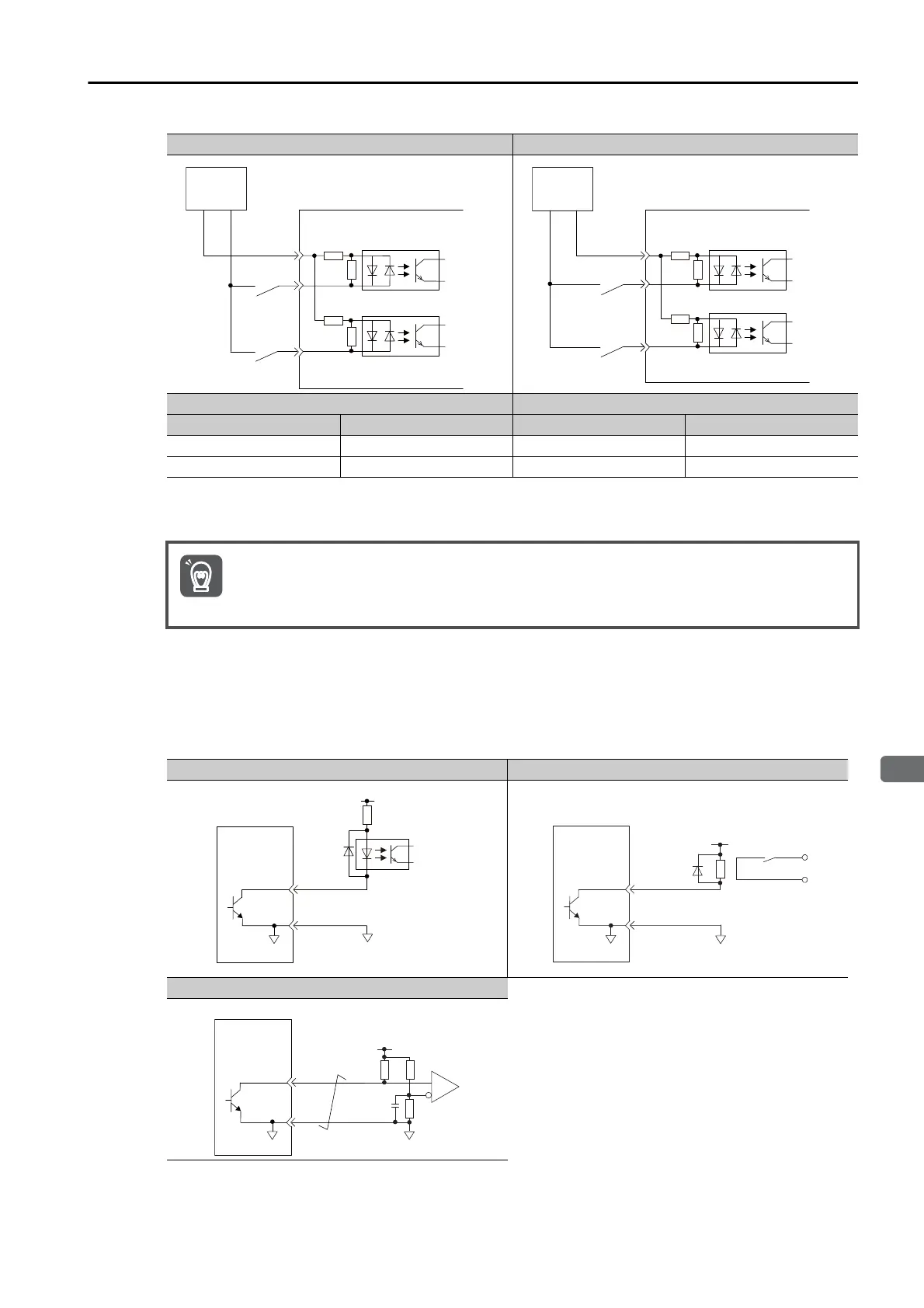
Sequence Output Circuits
Open-Collector Output Circuits
This section describes CN1 connector terminals 37 to 39 (Alarm Code Output).
The Alarm Code (ALO1, ALO2, and ALO3) signals are output from open-collector transistor
output circuits. Connect an open-collector output circuit to a photocoupler, relay, or line-
receiver circuit.
Note: The maximum allowable voltage and maximum allowable current for open-collector output circuits are as fol-
lows:
• Maximum allowable voltage: 30 VDC
• Maximum allowable current: 20 mA DC
Sink Circuits Source Circuits
Input Signal Polarity Input Signal Polarity
Photocoupler Internal Signal Level Photocoupler Internal Signal Level
ON Low level ON Low level
OFF High level OFF High level
Incorrect wiring or incorrect voltage application to the output circuits may cause short-circuit fail-
ures.
If a short-circuit failure occurs as a result of any of these causes, the holding brake will not work.
This could damage the machine or cause an accident that may result in death or injury.
Example for Photocoupler Circuit Example for Relay Circuit
Example for Line Receiver Circuit
SERVOPACK input side
Switch
Photocoupler
Internal
signal
level
Internal
signal
level
Photocoupler
Switch
24 V
+
−
SERVOPACK input side
24 V
+
−
Switch
Photocoupler
Internal
signal
level
Internal
signal
level
Photocoupler
Switch
Important
5 VDC to 30 VDC
Photocoupler
0V
0V
SERVOPACK
0V
Relay
5 VDC to 30 VDC
SERVOPACK
5 VDC to 30 VDC
0V
SERVOPACK

 Loading...


