6.1 I/O Signal Allocations
6.1.3 ALM (Servo Alarm) Signal
6-8
Example of Changing Output Signal Allocations
The following example shows disabling the /COIN (Positioning Completion) signal allocated to CN1-25
and CN1-26 and allocating the /BK (Brake) signal.
Refer to the following section for the parameter setting procedure.
5.1.3
Parameter Setting Methods
on page 5-6
Checking Output Signal Status
You can confirm the status of output signals on the I/O signal monitor. Refer to the following
section for information on the I/O signal monitor.
9.2.3 I/O Signal Monitor on page 9-5
6.1.3
ALM (Servo Alarm) Signal
This signal is output when the SERVOPACK detects an error.
Alarm Reset Methods
Refer to the following section for information on the alarm reset methods.
12.2.3 Resetting Alarms on page 12-40
6.1.4
ALO1 to ALO3 (Alarm Code) Signals
The ALO1 to ALO3 (Alarm Code) signals report alarms and warnings that occur in the SERVO-
PACK. Use the alarm code output signals as required to display the contents of the alarm at the
host controller (e.g., HMI).
Refer to the following sections for the relationship between the alarm code output and the
alarms/warnings.
12.2.1 List of Alarms on page 12-5
12.3.1 List of Warnings on page 12-45
Pn50E = n.
1
Pn50F = n.
0
Before change
↓↓
Pn50E = n.
0
Pn50F = n.
1
After change
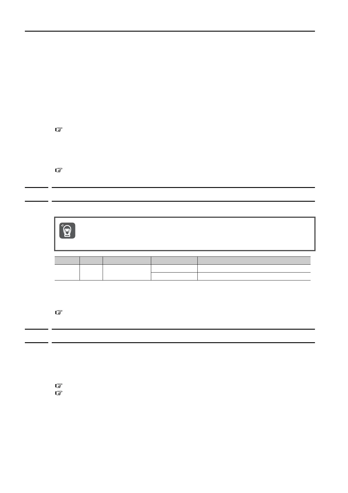
Configure an external circuit so that this alarm output turns OFF the main circuit power supply to
the SERVOPACK whenever an error occurs.
Type Signal Connector Pin No. Signal Status Meaning
Output ALM
CN1-31 and
CN1-32
ON (closed) Normal SERVOPACK status
OFF (open) SERVOPACK alarm
Important

 Loading...


