5.16 Electronic Gear Settings
5.16.2 Electronic Gear Ratio Setting Examples
5-50
5.16.2
Electronic Gear Ratio Setting Examples
Setting examples are provided in this section.
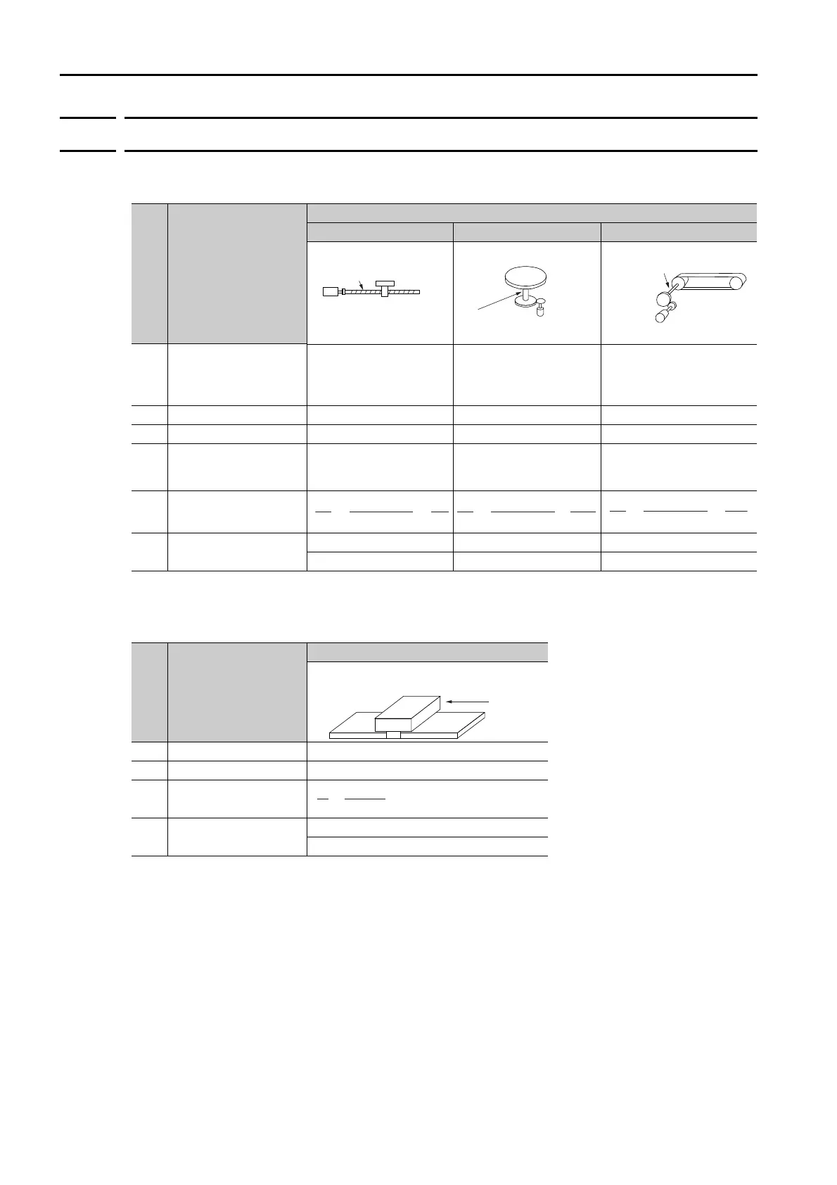
• Rotary Servomotors
• Linear Servomotors
A setting example for a Serial Converter Unit resolution of 256 is given below.
Step Description
Machine Configuration
Ball Screw Rotary Table Belt and Pulley
1
Machine
Specifications
• Ball screw lead: 6 mm
• Gear ratio: 1/1
•
Rotation angle per revo-
lution: 360
°
• Gear ratio: 1/100
• Pulley dia.: 100 mm
(Pulley circumference:
314 mm)
• Gear ratio: 1/50
2 Encoder Resolution 16,777,216 (24 bits) 16,777,216 (24 bits) 16,777,216 (24 bits)
3 Reference Unit 0.001 mm (1 μm) 0.01° 0.005 mm (5 μm)
4
Travel Distance per
Load Shaft Revolution
(Reference Units)
6 mm/0.001 mm =
6,000
360°/0.01° = 36,000
314 mm/0.005 mm =
62,800
5 Electronic Gear Ratio
6 Parameters
Pn20E: 16,777,216 Pn20E: 1,677,721,600 Pn20E: 838,860,800
Pn210: 6,000 Pn210: 36,000 Pn210: 62,800
Step Description
Machine Configuration
1 Linear encoder pitch 0.02 mm (20 μm)
2 Reference Unit 0.001 mm (1 μm)
3 Electronic Gear Ratio
4 Setting Parameters
Pn20E: 256
Pn210: 20
Reference unit: 0.001 mm
Load shaft
Encoder:
24 bits
Ball screw lead:
6 mm
Reference unit: 0.01°
Load shaft
Encoder: 24 bits
Gear ratio:
1/100
Reference unit: 0.005 mm
Load shaft
Gear ratio:
1/50
Pulley dia.:
100 mm
Encoder: 24 bits
16,777,216
6,000
1
1
=
×
B
A
B
A
16,777,216
36,000
100
1
=
×
B
A
16,777,216
62,800
50
1
=
×
Reference unit:
0.02 mm (20 m)
Forward direction

 Loading...


