6.6 Position Control
6.6.3 Reference Pulse Input Multiplication Switching
6-31
Setting the Clear Operation (Pn200 = n.X)
This parameter determines when the position error should be set to zero according to the con-
dition of the SERVOPACK. Set Pn200 = n.X (Clear Operation).
6.6.3
Reference Pulse Input Multiplication Switching
You can switch the input multiplier for the position reference pulses with the /PSEL (Reference
Pulse Input Multiplication Switch) signal. The number of reference pulses input to the SERVO-
PACK is multiplied by the reference pulse input multiplier. You can change the multiplier from 1
to a specified value n (n can be up to 100). You set the multiplier in Pn218 (Reference Pulse
Input Multiplier).
You can confirm if the multiplier was changed with the /PSELA (Reference Pulse Input Multipli-
cation Switching Output) signal.
This section describes the /PSEL (Reference Pulse Input Multiplication Switch) signal, the refer-
ence pulse input multiplier, and restrictions.
/PSEL (Reference Pulse Input Multiplication Switch) Signal
Use the /PSEL signal to change to the reference pulse input multiplier that is set in Pn218 (Ref-
erence Pulse Input Multiplier).
Note: You must allocate the /PSEL signal to use it. You can use the following parameters to allocate the signal to a
terminal.
• Pn50A = n.1 (Change the sequence input signal allocations.)
• Pn515 = n.X (/PSEL (Reference Pulse Input Multiplication Switching Input) Signal Allocation)
Refer to the following section for details.
6.1.1 Input Signal Allocations on page 6-4
/PSELA (Reference Pulse Input Multiplication Switching
Output) Signal
You can confirm if the reference pulse input multiplier was changed with the /PSELA (Reference
Pulse Input Multiplication Switching Output) signal.
Note: You must allocate the /PSELA signal to use it. You can use Pn510 = n.X (/PSELA (Reference Pulse
Input Multiplication Switching Output) Signal Allocation) to allocate the signal to a terminal. Refer to the fol-
lowing section for details.
6.1.2 Output Signal Allocations on page 6-6
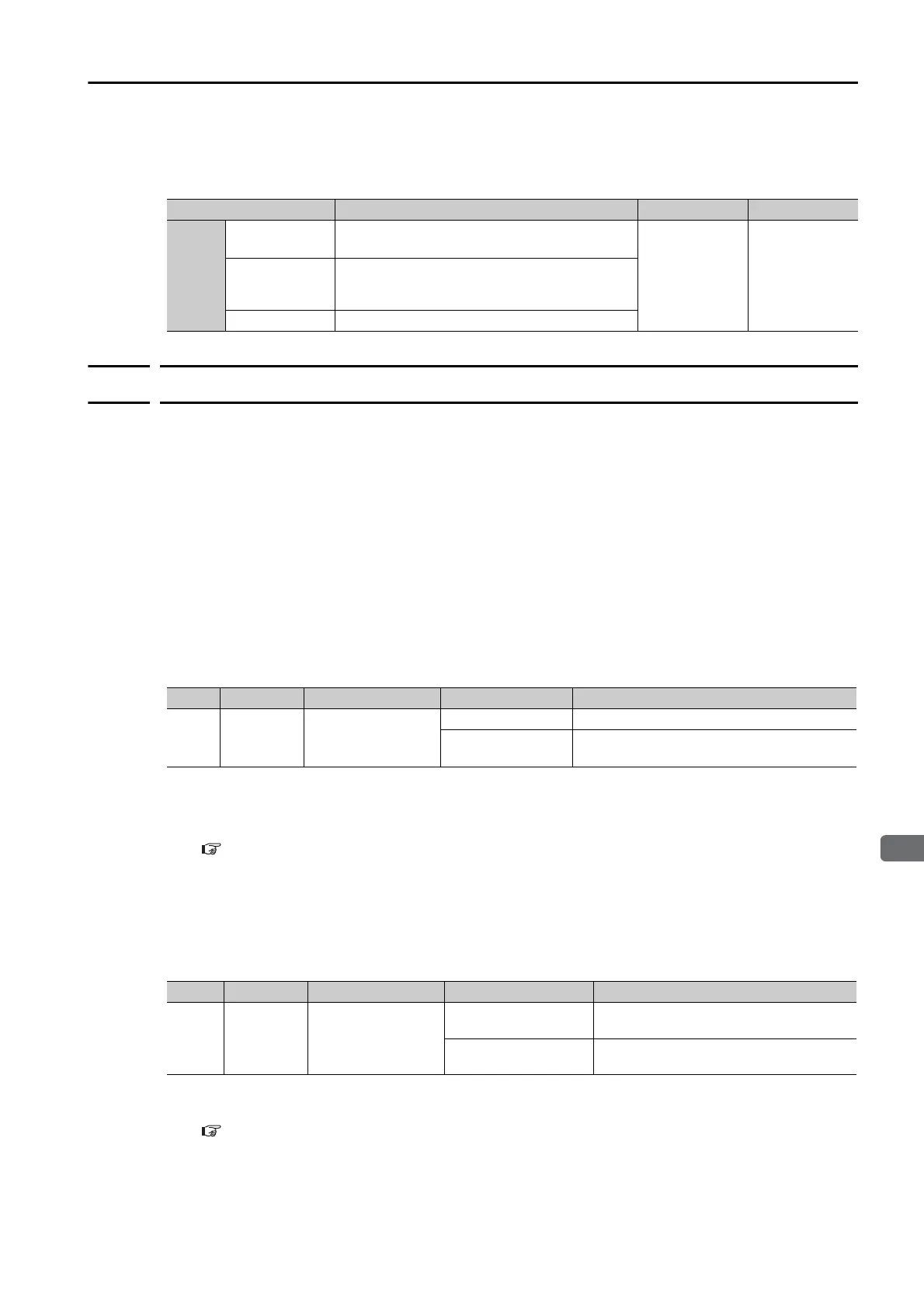
Parameter Meaning When Enabled Classification
Pn200
n.0
(default setting)
Clear position deviation at a base block (at
servo OFF or when alarm occurs).
After restart Setup
n.
1
Do not clear position deviation. The position
deviation is cleared only with CLR (Clear Posi-
tion Deviation) signal.
n.2 Clear position deviation when an alarm occurs.
Typ e Signal Connector Pin No. Signal Status Meaning
Input /PSEL Must be allocated.
ON (closed) Enables the reference pulse input multiplier.
OFF (open)
Disables the reference pulse input multiplier.
The multiplier will be 1.
Typ e Signal Connector Pin No. Signal Status Meaning
Output /PSELA Must be allocated.
ON (closed)
The reference pulse input multiplier was
enabled.
OFF (open)
The reference pulse input multiplier was
disabled.

 Loading...


