6.6 Position Control
6.6.7 Reference Pulse Inhibition Function
6-36
When Using the Default Input Signal Allocations (Pn50A = n.0)
When Changing Input Signal Allocations (Pn50A = n.1)
If you set Pn000 = n.X (Control Method Selection) to 1, 5, 7, or 8, the /INHIBIT signal is
used as the Reference Pulse Inhibit signal for reference pulse inhibition.
Note: You must allocate the /INHIBIT signal to use it. Use Pn50D = n.X (/INHIBIT (Reference Pulse Inhibit
Input) Signal Allocation) to allocate the signal to a connector pin. Refer to the following section for details.
6.1.2 Output Signal Allocations on page 6-6
Reference Pulse Inhibition Settings
To use reference pulse inhibition, set Pn000 = n.X (Control Method Selection) to 1, 5, 7 or
8.
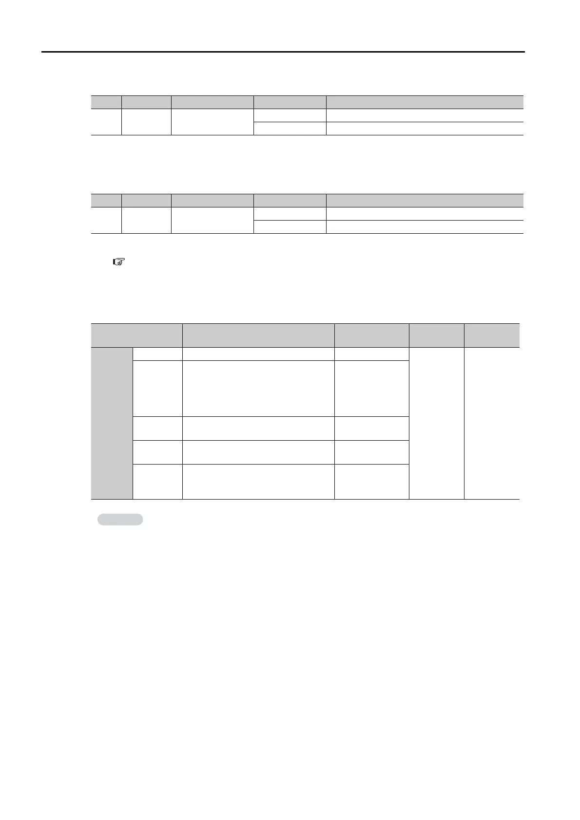
Typ e Signal Connector Pin No. Signal Status Meaning
Input /INHIBIT
CN1-41
(default setting)
ON (closed) Counting the reference pulses is stopped.
OFF (open) The reference pulses are counted.
Typ e Signal Connector Pin No. Signal Status Meaning
Input /INHIBIT Must be allocated.
ON (closed) Counting the reference pulses is stopped.
OFF (open) The reference pulses are counted.
Parameter Control Method
Used Input Sig-
nals
When
Enabled
Classifica-
tion
Pn000
n.
1
Position control /INHIBIT
After restart
Setup
n.
5
Switching between internal set
speed control and position control
/INHIBIT
/SPD-A
/SPD-B
/SPD-D
/C-SEL
n.
7
Switching between position control
and speed control
/INHIBIT
/C-SEL
n.
8
Switching between position control
and torque control
/INHIBIT
/C-SEL
n.
B
Switching between normal position
control and position control with
reference pulse inhibition
/INHIBIT
Counting reference pulses can be inhibited only for position control.

 Loading...


