<4. WIRING>
4-9
IM 01E30D01-01EN
Selection of HART 5/ HART 7
Output Signal
Code
-E -J
Ordering
Information
– Specify “5” Specify “7”
HART Protocol
Revision
HART 5 HART 7
Selec-
tion
guide
Require-
ment for
HART 7
function-
ality
NO
YES
Be sure to
conrmthe
protocol
revision of
the HART
congura-
tion tool
shown in
Note 2.
Other
condi-
tions
Not avail-
able to
switch to
HART 7
protocol
after deliv-
ery.
Available
to switch
to HART
7 proto-
col after
delivery by
user-con-
guration.
Available
to switch
to HART
5 proto-
col after
delivery by
user-con-
guration.
Remarks Note 1 Note 2 Note 2
Note 1: "-E" is HART5 exclusive model and will be terminated.
"-J" is recommended for HART communication.
Note 2: HART protocol revision for the device and HART
congurationtool
HART 7 communication is supported by FieldMate
R2.04 or later.
Protocol revision supported by HART
congurationtool
5 7
AXR,HART5 Available Available
AXR,HART7 Not available Available
(2) Pulse Output, Status Output, Alarm Output
One Output can be selected from pulse, alarm, or
status through the parameter setting.
Read Table 4.6.2 or Table 4.6.5 as wiring examples.
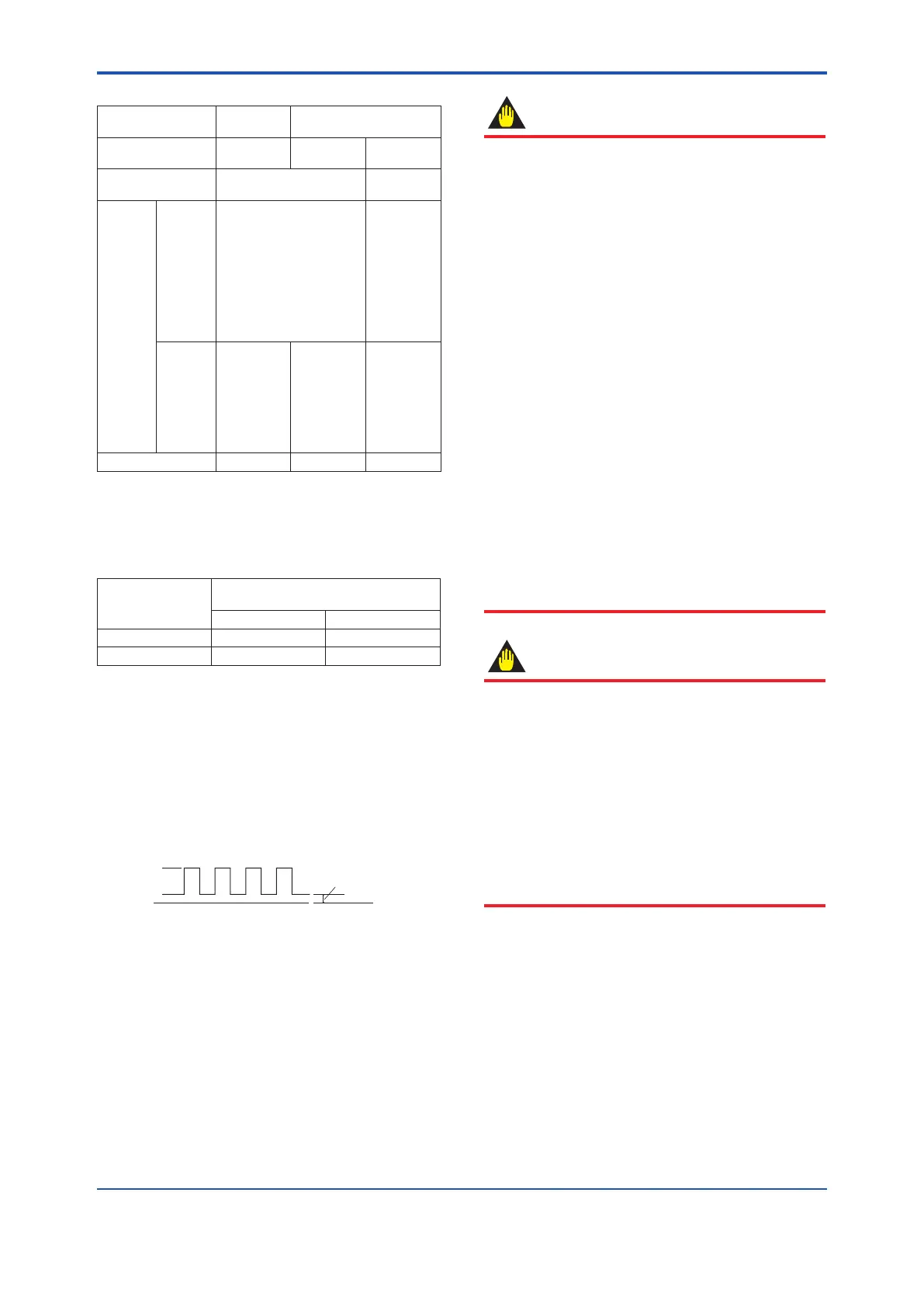
Digital Output:
Transistor contact output, open collector
Contact rating: 30 V DC, 120 mA DC
Low level: 0 to 2 V DC (Read Figure 4.6.4)
LOW level
0 to 2 V
Figure 4.6.4 High and Low levels (transistor contact
output)
IMPORTANT
Precaution for Pulse Output
• Asthisisatransistorcontact(insulated
type), give attention to proper voltage and
polarity when wiring.
• Donotapplyavoltagelargerthan30VDC
or a current larger than 120 mA in order to
prevent damage to the instrument.
• Wheninputlterconstantoftheelectronic
counter is large in relation to the pulse width,
the signal will decrease and the count will not
be accurate.
• Iftheinputimpedanceoftheelectronic
counter is large, an induction noise from
the power supply may result in inaccurate
counts.Useashieldcableorsufciently
reduce the input impedance of the electronic
counterwithintheelectromagneticowmeter
pulseoutputspecicationrange.
• Theloadresistanceforpulseoutputis
necessary. Read Table 4.6.3 or Table 4.6.6.
• Neithernoloadresistancenortoosmall
value of load resistance for pulse output will
give a damage to the instrument.
IMPORTANT
Precaution for Status Output and Alarm Output
• Asthisisatransistorcontact(insulated
type), give attention to proper voltage and
polarity when wiring.
• Donotapplyavoltagelargerthan30VDC
or a current larger than 120 mA in order to
prevent damage to the instrument.
• ThisoutputcannotswitchanACload.To
switch an AC load, an intermediate relay
must be inserted as shown in Table 4.6.2 or
Table 4.6.5.
* The alarm output operates from open
(normal) to closed (alarm occurrence) in the
default value (as setup upon plant shipment).
Changes can be made via the parameter
settings.

 Loading...

