<6. PARAMETER DESCRIPTION>
6-33
IM 01E30D01-01EN
NOTE
• If the setting value for the low limit is not less
than the high limit value (as set using J12: 4-
20mA High Lmt), the setting alarm “54: 4-20
Lmt Err” will be displayed.
• This parameter has no effect on pulse output
or the totalization function.
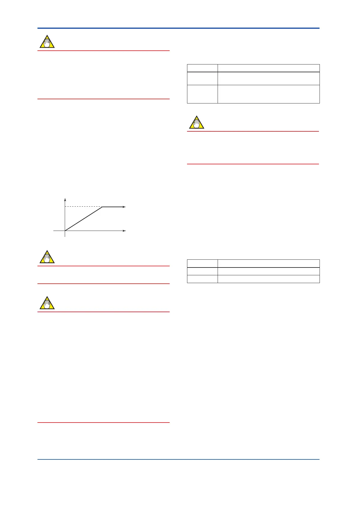
[J12: 4-20mA High Lmt] Setting of the high limit for
current output
This parameter is used to restrict high current
portions of current (4 to 20mA) output, and it is
initially set to 103.13%. Setting should be performed
when a lower value is required for the higher limit.
Theindicationsoftheinstantaneousowrates(%,
Actualinstantaneousowrate,mA,Bargraph)on
the display unit are the same action.
Example: Situation where high limit is set to 90%
4mA
NOTE
When the high limit works, the display indicates
83:Fix Cur Wng as the warning.
NOTE
The set current output at each alarm function
becomes higher priority than set value at J12
when the alarm occurs.
The priority of this output is described below.
The process alarms and setting alarms are
available when “Yes” were selected at G26,
G27, G28, G29 and/or G31.
System alarm (G20) >
Process alarm (G25) >
Setting alarm (G30) >
High limit (J12)
Example: “21.6mA or more” is set for G25
The current output is 21.6mA or more
in spite of setting any value at J12.
[J15: Pulse Special Mode] Selection of the pulse
special mode
This parameter is used to set the pulse mode only
instead of using current output.
Setting Function
Normal Select this parameter when the current output or
Simultaneous Current-Pulse output is used.
Pulse Only Select this parameter when the pulse output as
pulse special mode is used only.
Thecurrentoutputisxedat12mA.
NOTE
The pulse output function does not work unless
setting the “Pulse Output” at F10:DO Function
when the “Pulse only” is selected at J15:Pulse
Special Mode.
[J20: Flow Direction] Settingoftheowdirection
Upon shipment from the manufacturing plant,
thesystemissetupsuchthatowinthesame
direction, as shown by the direction of the arrow
markontheowtube,willbemeasuredasforward
ow;however,thisparametercanbeusedtoset
“Reverse”sothatowintheoppositedirectionto
the arrow mark will be treated as forward.
Note: This function does not apply to measurement in both the
forward and reverse directions, although this can be setup
using by selecting “Fwd/Rev Rngs” from either F10: DO
Function.
Setting Function
Forward Forward direction corresponds with arrow mark.
Reverse Forward direction is opposite to arrow mark.
[J21: Rate Limit] Setting of the rate limit value
● This parameter is used in situations where
sudden noise cannot be eliminated by
increasing the damping time constant.
● In situations where step signals or sudden
noise signals caused by slurries or the like
are entered, this parameter is used to set the
standard for determining whether an input
correspondstoaowmeasurementornoise.
Specically,thisdeterminationismadeusing
upper and lower rate limits and using the dead
time.
● Rate limit values are set using a percentage of
the smallest range. The range of deviation per
one calculation cycle should be input.

 Loading...

