<6. PARAMETER DESCRIPTION>
6-34
IM 01E30D01-01EN
[J22: Dead Time] Setting of dead time
This parameter sets the time for application of the
rate limit, and if a value of 0 is set, the rate limit
function will be terminated.
NOTE
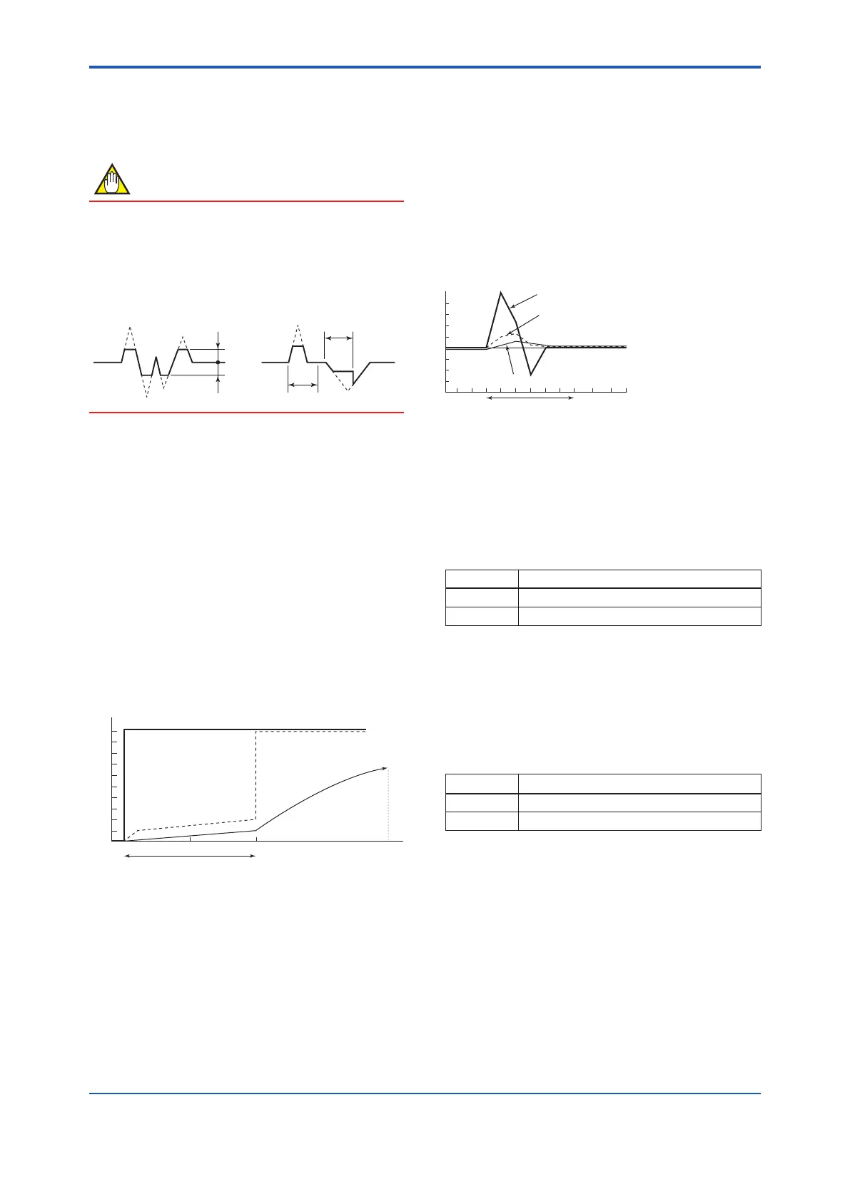
Determining rate limit value and dead time
T0
T0
2%
2%
Rate limit value:
Determines the level for
output fluctuation cutoff. For
example, if this is set to 2%,
noise above 2% will be
eliminated as shown in the
diagram.
Dead time (T
0
This is to be determined using
the output fluctuation width. If
noise exceeds the dead time
as shown in the diagram
below, the dead time should
be made longer.
● Signal processing method:
Axedupperandlowerlimitvalueissetupwith
respect to the primary delay response value for
theowratevalueobtainedduringtheprevious
sampling,andifthecurrentlysampledowrate
is outside these limits, then the corresponding
limitisadoptedasthecurrentowratevalue.
In addition, if signals which breach the limits in
the same direction occur over multiple samples
(i.e., within the dead time), it is concluded that
thecorrespondingsignalisaowratesignal.
Example 1: Step input
%
1%
Step signal
Flow rate value
after rate limit
processing
63.2
%
100 225
Dead time: 3 s
Input: 0 to 10%
Damping time constant: 5 s
Dead time: 3 s
Rate limit value: 1%
Flow rate value after
damping
(a)
(b)
(c)
(d)
(1) In comparison with the previous value at (a), it
is determined that the signal is in excess of the
rate limit value and the response becomes 1%.
However, the actual output applies damping,
and therefore the output turns out to be as
indicated by the solid line.
(2)Subsequentowvalueswithinthedeadtime
zone correspond to signals of post-damping
owvalue+ratelimitvalue(1%).
(3) Since input signals do not return to within
the rate limit value during the dead time, it is
determinedat(c)thatthissignalisaowrate
signal.
(4) The output signal becomes a damped curve
and compliance with the step signal begins.
Fivesecondsafterdeterminationofaowrate
signalintheabovegure,alevelof63.2%is
reached.
Example 2: Slurry noise
+1%
-1%
Flow rate value after damping
Flow rate value
after rate limit
processing
Slurry noise
Input: 0 to 10%
Damping time constant: 1 s
Dead time: 1 s
Rate limit value: 1%
Time
In the figure on the left, it
is determined that the
slurries noise signal is not
a flow rate signal.
[J23: Pulsing Flow]Selectionofpulsingow
support
Inasituationwherepulsatingowcauseserrorin
theaverageowvalue,duetotheapplicationofa
plunger pump, this parameter provides functionality
whereby calculation is controlled and variations in
owratearefollowed.
Setting Function
No Normal
Yes Support for pulsingow
[J25:T/PDampSelect] Setting of damping
operation
Thisparameterisusedtoselectthattheowrate
value obtained through damping calculation for
totalization and pulse output or the instantaneous
owratevalue(nodamping)fortotalizationand
pulse output.
Setting Function
Damp Damping
No Damp No damping

 Loading...

