Axio Imager 2 OPERATION ZEISS
Illumination and contrast methods
01/2016 430000-7544-001 173
• Push the analyzer slider (Fig. 199/1) into the respective slot or swivel in the analyzer module
(Fig. 199/4) on the reflector turret. The field of view appears dark due to the crossed polarizers.
If you work with the analyzer slider on the Axio
Imager 2, swivel the reflector turret to a blank
turret position.
• Move the specimen feature you want to examine into the field of view and rotate it with the rotary
stage Pol through 360°. When rotated between crossed polarizers, birefringent (anisotropic)
specimens should now show the variations in color and intensity described above. However, optically
anisotropic substances may also remain dark if an isotropic direction, e.g. of optically uniaxial or biaxial
crystals, is oriented parallel to the direction of observation.
4.12.5.2 Determining the vibration direction n
'
(1) Application
The determination of the vibration directions of n
γ
and n
γ
' (vibration direction with the highest absolute
or relative refractive index) and n
α
and n
α
' (vibration direction with the lowest absolute or relative
refractive index) in relation to the morphological directions, e.g. of crystal surfaces, crystal needles or
fibers, provides an important recognition criterion. It is also used for the diagnosis of biocrystals (e.g.
gout, pseudo-gout).
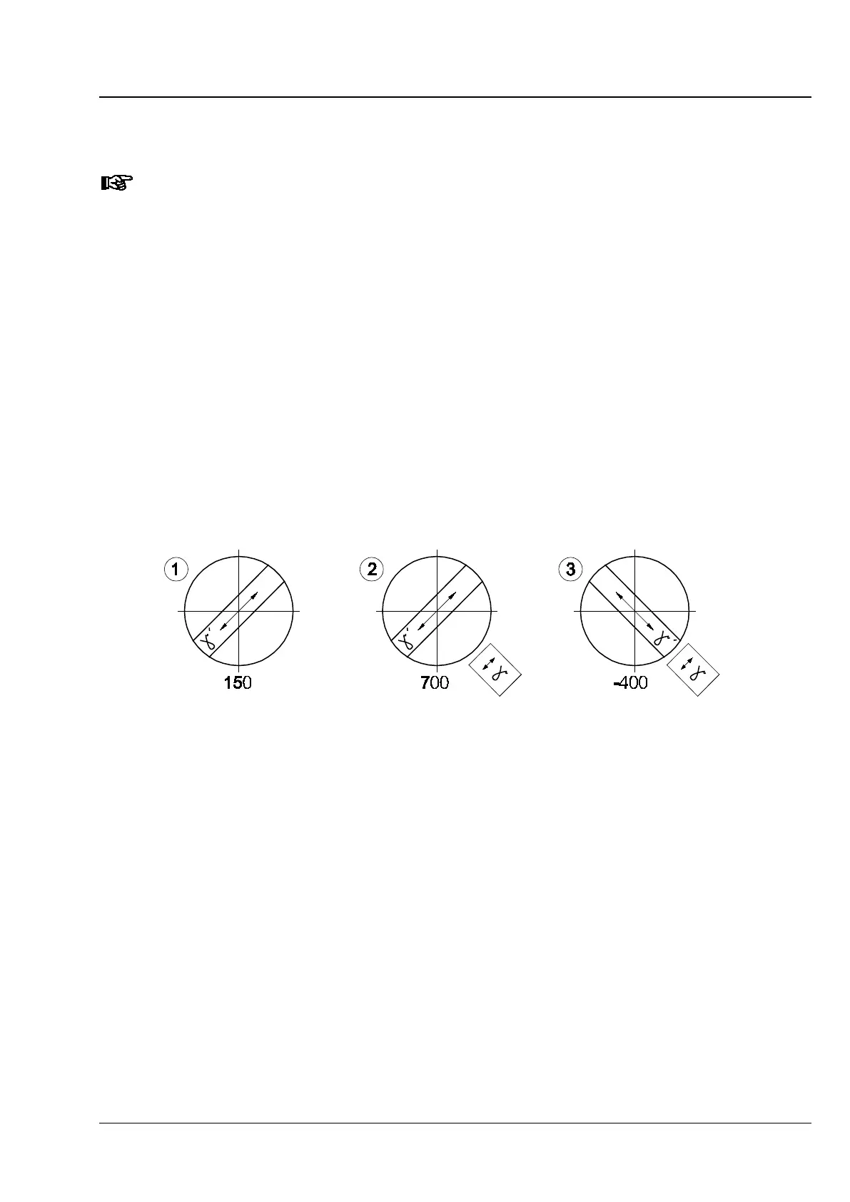
Fig. 200 Determining the vibration direction n
‘
based on the example of a synthetic fiber
(2) Instrument equipment
− Phototube Pol
− Achromatic-aplanatic universal condenser Pol
− Strain-free objectives
− Rotary stage Pol
− Polarizer D (rotatable or fixed)
− Analyzer slider or analyzer module D in reflector turret (only on microscopes equipped with a reflector
turret)