ZEISS OPERATION Axio Imager 2
Illumination and contrast methods
172 430000-7544-001 01/2016
4.12.5 Setting transmitted-light polarization for orthoscopic observation
Magnified viewing (e.g. of a thin section) in polarized light is called orthoscopy (Greek: orthos = straight;
skopein = seeing) because illumination is by "straight" light rays which travel parallel to the microscope
axis, with the aperture diaphragm almost closed.
4.12.5.1 Detecting birefringence
(1) Application
The technique of transmitted-light polarization is used for specimens that change the state of polarization
of light. These specimens - including crystals, minerals or polymers - are called birefringent. When these
birefringent substances are viewed between crossed polarizers (polarizer ⊥ analyzer), they appear
brightened, while their surroundings remain dark.
Birefringent substances are identified by the fact that they exhibit four bright and four dark positions
when rotated through 360° between crossed polarizers. Dependent on the birefringence, thickness and
orientation of the specimen, interference colors ranging from gray (mostly with biological specimens) to
white, yellow, red and blue appear in this process. These interference colors can be of the first or any
higher order.
(2) Instrument equipment
− Phototube Pol
− Achromatic-aplanatic universal condenser Pol
− Strain-free objectives
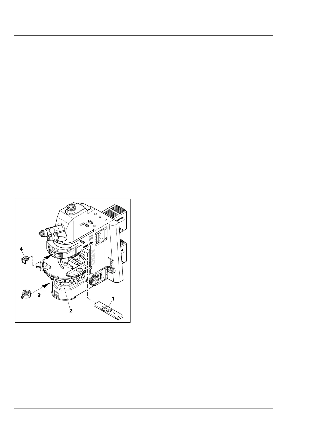
− Rotary stage Pol (Fig. 199/2)
− Polarizer D (rotatable or fixed) (Fig. 199/3)
or
polarizer integrated in the turret disk of the
condenser
− Analyzer slider (Fig. 199/1) or analyzer module
D (Fig. 199/4) in reflector turret (only on
microscopes equipped with a reflector turret)
(3) Setting the microscope
• Set the microscope as for transmitted-light
brightfield according to KÖHLER (see
Section 4.12.1 (3)).
• Center rotary stage Pol (Fig. 199/2) and
objectives (if not yet completed – see
Section 3.36.3).
• Swivel polarizer (Fig. 199/3) into the light path
and, if it is rotatable, turn it to 0°.
Fig. 199 Components for transmitted-light
polarization