Axio Imager 2 FIRST-TIME SET-UP ZEISS
Mechanical stage 75x50 mot. CAN
01/2016 430000-7544-001 79
3.37.2 Assembling mechanical stage 75 x 50 mot. CAN and connecting joystick / trackball
On delivery, the mechanical stage has a transport lock. This should be removed before attaching
the stage, as otherwise the mechanical stage could be damaged.
• Unpack the mechanical stage and remove the transport lock (Fig. 70/2).
• Place mechanical stage (Fig. 70/1) onto the stage carrier so that the holes in the underside of the
mechanical stage coincide with the through holes of the stage carrier.
• Using the angled Allen key (AF 3), screw four screws (Fig. 70/6) from the bottom into the underside of
the stage, with the shorter screws being inserted in the front holes.
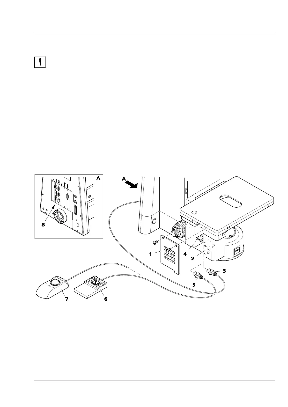
• Remove cover (Fig. 72/1) by loosening the two screws.
• Depending on which is used, insert the CAN connecting plug (Fig. 72/5) of the joystick (Fig. 72/6) or
the trackball (Fig. 72/7) into the connection socket on the mechanical stage (Fig. 72/4).
• Connect the CAN connection socket on the mechanical stage (Fig. 72/2) to that on the rear of the
stand (Fig. 72/8) using a CAN-bus cable (Fig. 72/3).
• Replace the cover (Fig. 72/1).
Fig. 72 Assembling mechanical stage 75 x 50 mot. CAN and connecting joystick / trackball