Axio Imager 2 OPERATION ZEISS
Illumination and contrast methods
01/2016 430000-7544-001 189
4.12.10 Setting reflected-light TIC
(1) Application
The reflected-light TIC technique (microinterferometry; TIC = Total Interference Contrast in circularly
polarized light) can be used to image and measure object structures available in different azimuths.
(2) Instrument equipment
− Axio Imager MAT with connected and adjusted
HAL 100 halogen illuminator.
− EC Epiplan-Neofluar, Epiplan objectives
additionally labeled "DIC" or "Pol".
− 6x20 compensator mount or 4-position
modulator turret
− 6x20 TIC slider with accompanying C DIC P&C
reflector module.
(3) Setting reflected-light TIC
• Place the specimen (e.g. a step-shaped object)
on the stage and prepare the microscope as
described in Section 4.12.7 for reflected-light
brightfield.
• Rotate the reflector turret to swing C DIC P&C
reflector module into the light path.
• Push the 6x20 TIC slider into the 6x20
compensator mount (Fig. 206/4) or rotate turret wheel (Fig. 207/5) of the 4position modulator turret
(Fig. 206/6) into TIC-Position (TIC). Colored interference fringes appear in the field of view. Turn the
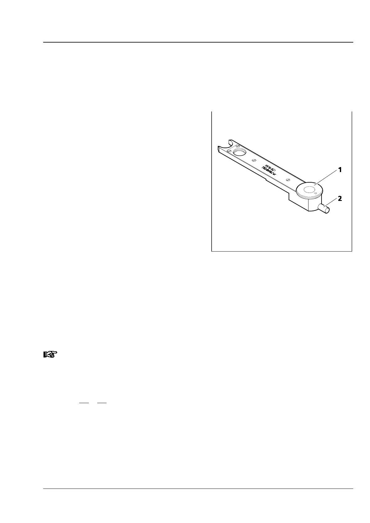
setscrew (Fig. 209/2) of the TIC slider or the modulator turret to shift the black interference fringe until
it appears to be in the center of the field of view.
• To select the structure to be measured, turn control wheel (Fig. 209/1) of the TIC slider or modulator
turret until the interference fringe system is vertical to the splitting direction of the specimen (see
Fig. 210). The interference fringes can be shifted by means of setscrew (Fig. 209/2) of the TIC slider or
the modulator turret.
Refer to Section 4.12.9
(5) for the use of the motorized four-
position modulator turret for the
reflected-light TIC technique.
The step height is then determined using the following formula:
where: d = step height in nm
n = refractive index of the environment, usually air (n = 1)
∆ = path difference
a = spacing of interference fringes
b = offset of interference fringes at the step
λ = wavelength of the illumination in nm
Fig. 209 6x20 TIC slider