Axio Imager 2 FIRST-TIME SET-UP ZEISS
Changing the beam splitter in the reflector module FL P&C
01/2016 430000-7544-001 43
If it is necessary to mount filters that carry no
directional mark (arrow), the following procedure
is recommended:
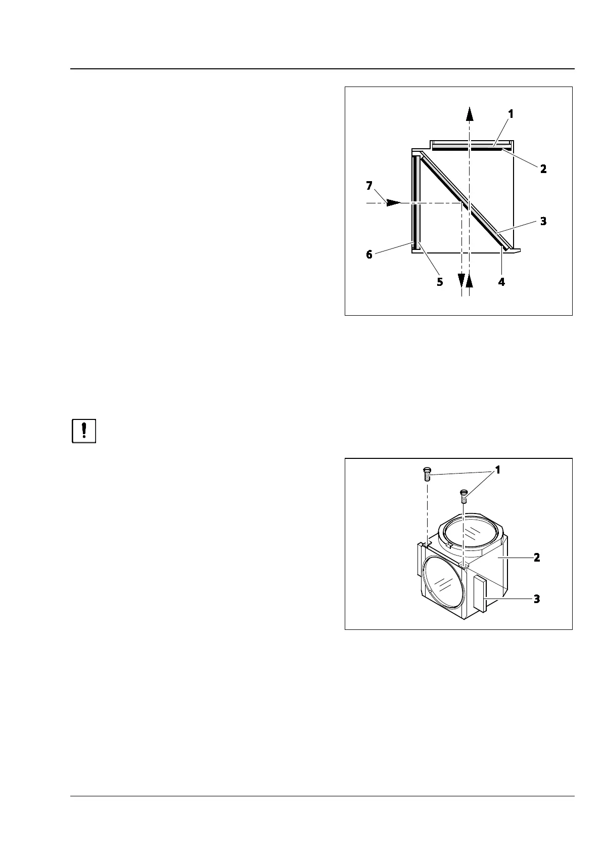
Mount the filters with the reflective dielectric layers
in such a way that the reflective layer (Fig. 21/6) on
the exciter filter (Fig. 21/5) points outwards
(relative to the reflector module). On the barrier
filter (Fig. 21/1), the reflective layer (Fig. 21/2)
points inwards (Fig. Fig. 21).
The reflective layer (Fig. 21/4) of the beam splitter
(Fig. 21/3) should point downward when in its
mounting position.
The arrows (Fig. 21/7) mark the illumination and
imaging beam path.
3.13 Changing the beam splitter in the reflector module FL P&C
When mounting filters and beam splitters, take extreme care to prevent damage to and
contamination of the optical components.
We recommend ordering fully equipped FL P&C
reflector modules, since changing the beam splitter
is a challenging task.
However, if you should choose to change the
beam splitter, follow this procedure:
• Remove the FL P&C reflector module from the
reflector turret (also refer to Section 3.11.2).
• Unscrew the two slotted screws (Fig. 22/1) with
a screwdriver.
• Hold both halves of the reflector module
together (emission half (Fig. 22/2) and
excitation half (Fig. 22/3), turn to the position
opposite the installation position and put it
down.
Fig. 21 Installing filter and beam splitter
Fig. 22 Changing the beam splitter