ZEISS FIRST-TIME SET-UP Axio Imager 2
Changing the beam splitter in the reflector module FL P&C
44 430000-7544-001 01/2016
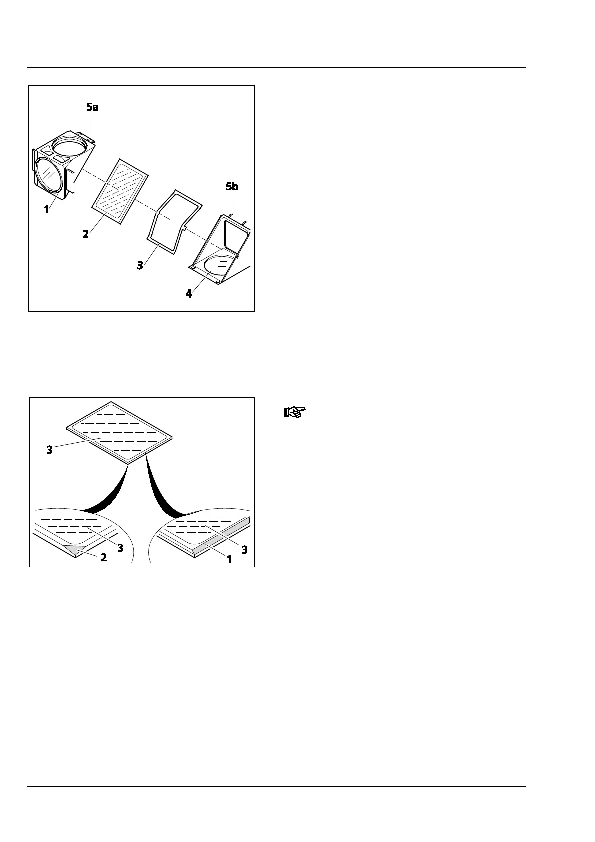
• Tip up the excitation half of the module
(Fig. 23/1), which now is on top, and remove it
from the retaining pins (Fig. 23/5b) on the
bottom emission half of the module
(Fig. 23/4).
• Remove the beam splitter (Fig. 23/2) and spring-
loaded frame (Fig. 23/3) from the bottom half
of the module.
• Remove the old beam splitter and carefully
place the new one onto the spring-loaded
frame (Fig. 23/3) with the reflective side facing
up. Then insert both parts together into the
bottom half of the module. Ensure that the side
tongue of the spring-loaded frame is in the
appropriate recess in the bottom half of the
module.
The reflective (coated) side (Fig. 24
/3)
of the beam splitter has a beveled
edge (Fig. 24/1) or corner (Fig. 24/2).
• Place the excitation half of the module
(Fig. 23/1) onto the emission half (Fig. 23/4)
(retaining pins Fig. 23/5b and eyelets Fig. 23/5a
mesh with one another). Hold both halves
together and turn them back into the
installation position.
• Re-insert the slotted screws and tighten them.
• Finally, affix the adhesive label with the name of
the filter combination to the side of the module.
Fig. 23 Changing the beam splitter -
Continued
Fig. 24 Labelling of beam splitter