IES-2000/3000 User’s Guide
2-2 Installation and Configuration with the EEC1020
2.3 Hardware Installation Procedure
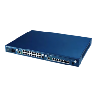
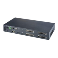
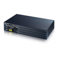
Please follow the procedure below to install the IES-2000/3000 chassis and cards. See Chapter 3 Hardware
Overview for safety warnings and hardware graphics.
Step 1. Make sure the power switch is in the OFF position.
Step 2. Install and fasten the IES-2000/3000 main and splitter chassis to the rack with the main chassis above
the splitter chassis.
Step 3. Connect the frame ground (on the lower rear panel of the IES-3000 and the lower left corner of the
front panel on the IES-2000) before connecting any other cables or wiring.
Step 4. If a PWR-2000 is required, install the PWR-2000 in the rack. Make sure the power switch on the PWR-
2000 is in the
OFF position before connecting the power cord to an AC outlet.
Step 5. Connect the power terminals of the IES-2000/3000 to the power supply. Connect the terminal labeled
–48V on the IES to the –48V terminal on the power supply. Repeat the step for the terminal labeled
RTN.
Step 6. If either the extension card (EEC1020) or the line cards are not already installed, follow the procedure
below to install them. Keep in mind that the extension card EEC1020 must be installed in slot 1 on the
IES-2000 and slot 8 or 9 on the IES-3000.
• Install the cards starting from the bottommost (IES-2000) or the leftmost (IES-3000) slot.
• Grasp the center of the front panel of the card with one hand and place the other hand under the
card to support it.
• Insert the card halfway into the slot and spread the two ejector levers outward. Make sure the levers
are perpendicular to the front panel.
• Slide the card into the slot until it makes contact with the backplane. The levers should be at a small
angle to the front panel now.
• Push on the two ejector levers firmly until they are flush with the front panel.
• Tighten the two thumbscrews.
Step 7. Do NOT connect the extension card to a switch yet.
Step 8. Turn on the power.
2.4 Configuring the Line Cards
Please follow the procedure below to configure the individual line cards. The procedure must be followed exactly;
otherwise, you may interrupt the normal operation of your network.
Step 1. Using a crossover Ethernet cable, connect the Ethernet port on the computer to the first Ethernet port of
a line card (the port labeled n-1 on EEC-1020, where n is the slot number) on the IES-2000. On the
IES-3000, there is only one Ethernet port per slot and you can use the 1-16 numbering on the EEC1020.
Step 2. Each line card leaves the factory with a default IP address of 192.168.1.1 and a subnet mask of
255.255.255.0.

 Loading...
