IES-2000/3000 User’s Guide
3-8 Hardware Overview
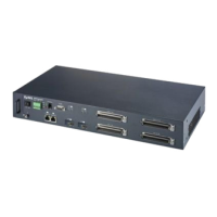
3.3.3 IES-3000ST/SW Rear Panel Connections
The DSL splitter cards separate each line’s high frequency DSL signal from the voice band signal and feed the
DSL signal to the DSL line card, while the voice band signal is diverted to the CO Telco-50 connector (or wire
wrapping pins) on the splitter chassis’s rear panel.
Connect the USER Telco-50 connector (or wire wrapping pins) to the subscribers’ telephone wiring. In most
multi-tenant unit applications, the USER pins connect to the subscribers’ telephone wiring via Main Distribution
Frame (MDF), see 3.4 MDF Scenarios for details. 24 DSL line connections are available when using the ALC and
SLC and 12 are available with the VLC.
Connect the CO Telco-50 connector (or wire wrapping pins) (pins 2-25 and 27-50) to the telephone company; see
the pin assignments appendices for details. In most multi-tenant unit applications, the CO pins connect to the
telephone company via MDF; see 3.4 MDF Scenarios for details. 24 CO phone line connections are available
when using the ASC and 12 are available with VLC.
3.4 MDF Scenarios
Images of the IES-3000ST (Splitter chassis with Telco-50 connectors) rear panel are used throughout this chapter.
Connections for the splitter chassis with wire wrapping pins use the same pin assignments.
The following figure gives an overview on a possible installation scenario for the IES. DSL and voice signals can
coexist on the same telephone wiring.
 Loading...