Chapter 3 Hardware, Interfaces and Zones
USG FLEX H Series User’s Guide
56
4 Close Cable Clamp B to secure the power cord to the power socket.
3.4 Default Zones, Interfaces, and Ports
The default configurations for zones, interfaces, and ports are as follows. References to interfaces may
be generic rather than the specific name used in your model. For example, this guide may use “the
WAN interface” rather than “wan1” or “wan2”, “ge2” or” ge3”.
Each Zyxel Device port can be configured as an additional WAN, LAN, WLAN or DMZ port.
The following table shows the default physical port and interface mapping for each model at the time
of writing.
The following table shows the default interface and zone mapping for each model at the time of
writing.
Table 21 Default Physical Port – Interface Mapping
PORT / INTERFACE P1 P2 P3 P4 P5 P6 P7 P8 P9 P10 P11 P12 P13 P14
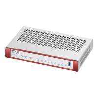
USG FLEX 100H/USG
FLEX 100HP
ge1 ge2 ge3 ge3 ge3 ge3 ge4 ge4
USG FLEX 200H/USG
FLEX 200HP
ge1 ge2 ge3 ge3 ge3 ge3 ge4 ge4
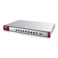
USG FLEX 500H ge1 ge2 ge3 ge3 ge3 ge3 ge4 ge4 ge4 ge4
USG FLEX 700H ge1 ge2 ge3 ge3 ge3 ge3 ge4 ge4 ge4 ge4
Table 22 Default Zone – Interface Mapping
ZONE / INTERFACE WAN LAN
USG FLEX 100H/USG
FLEX 100HP
GE1
GE2
GE3
GE4
USG FLEX 200H/USG
FLEX 200HP
GE1
GE2
GE3
GE4
Table 23 Default Zone – Interface Mapping
ZONE / INTERFACE WAN LAN
USG FLEX 500H GE1
GE2
GE3
GE4
USG FLEX 700H GE1
GE2
GE3
GE4
 Loading...