Page 76 February 2020 – TD 266 OPERATING MANUAL – ZPulse® DCS 4420/4830/4520/4930
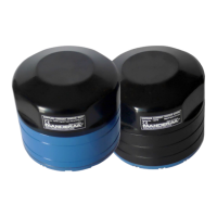
The DCS System Configuration is divided in three different sheets.
Sheet 1/3 contain settings for Meassurement settings.
Ping Number is the number of ping transmitted during one recording
interval. One ping is a transmitted pulse on both axes, so one pulse on
two transducers.
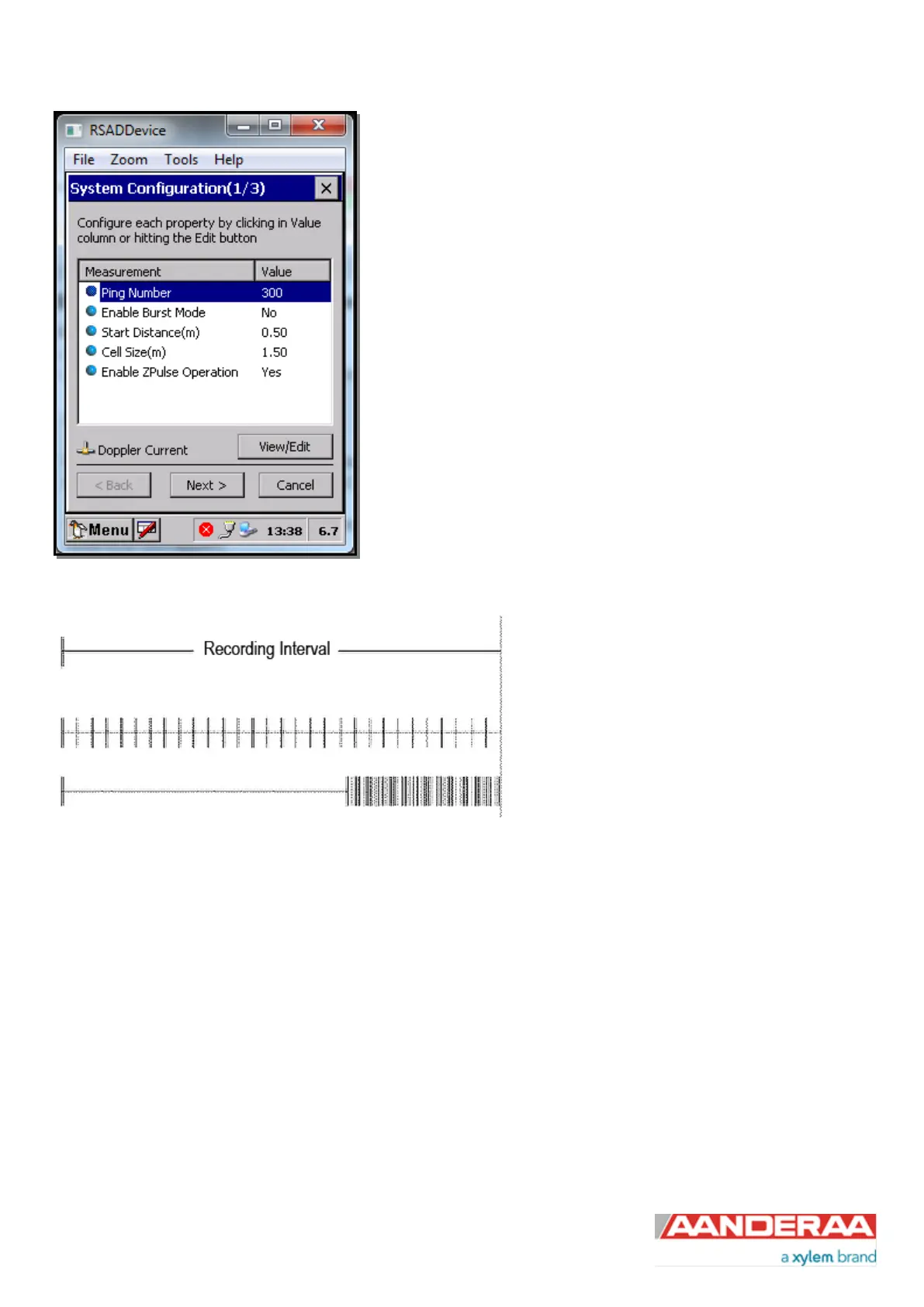
Enable Burst Mode. The sensor can run in burst mode or spread mode.
When burst mode is enabled the sensor performs all ping measurements
at the end of the recording interval. If it is disabled the ping
measurements are evenly spread out during the recording interval. The
instrument activates sleep mode between each measurement, which
reduces the power consumption. Power consumption in spread and burst
mode is about the same.
Figure 5-4: Measurement
Spread Mode
Burst Mode
Figure 5-5: Spread mode and burst mode ping distribution during the recording interval
The transmitted pulse has a fixed length of 0.75m. Internal ringing in the transducers will always occur after transmitting
acoustic pulses; the transducers cannot receive backscattered signal until the ringing stops. For the ZPulse DCS the
pulse must have travelled at least a distance of minimum 0.4m before backscattered signals from the pulse can be
received by the transducers. This is called the Start Distance. The transducers continue to receive backscattered signal
from particles present in the beam until the pulse has propagated a distance equal to the Cell Size.
The total area from which the DCS receives backscattered energy is called the Measurement Area. Due to the shape of
the pulse, the main contribution to backscattered energy is from particles that are present in an area around the Cell
Centre. The measurement area outside the cell contributes very sparsely to the measured Doppler frequency shift.
Refer Figure 5-6 for an illustration.
Surrounding objects must be further away from the DCS than the described measurement area to avoid influencing the
measurements.