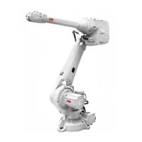
Refitting the stop pin, axis 1
Use this procedure to refit the stop pin axis 1.
NoteAction
DANGER
Turn off all:
• electric power supply
• hydraulic pressure supply
to the robot, before entering the robot
working area.
1
Clean the joints that have been opened. See
Cut the paint or surface on the robot before
replacing parts on page 201
2
See the figure in
• Location of stop pin axis 1 on
page 301
Fit the two o-rings on the stop pin.
Note
The o-rings are not used when bracket (D)
is installed.
3
xx0800000453
Fit the stop pin on the bracket.
Note
The small spike on the bracket shall be
pointing downwards for correct fitting of the
stop pin.
4
Parts:
• A: Bracket
• B: Stop pin
• C: Small spike
3HAB7116-1 (Loctite 243).Secure the stop pin together with bracket
(D) on the frame with its attachment screws.
Use Locking liquid
5
Tightening torque: 10 Nm
See the figure in
• Location of stop pin axis 1 on
page 301
Seal and paint the joints that have been
opened. Also repair possible damages of
the special Foundry Prime paint coat of the
robot. See Cut the paint or surface on the
robot before replacing parts on page 201.
6
Continues on next page
Product manual - IRB 4600 Foundry Prime 303
3HAC040585-001 Revision: M
© Copyright 2013-2018 ABB. All rights reserved.
4 Repair
4.6.1 Replacing stop pin axis 1
Continued

 Loading...