Illustration/NoteAction
For the location of the connector XP7, see
Single Cabinet Controller on page 121.
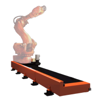
For the robot track and transfer track with
3-axis SMB box:
Disconnect the power cable connector XP7
from the controller.
1
For the location of the connector XP1, see
Single Cabinet Controller on page 121.
For the transfer track with 6-axis SMB box:
Disconnect the power cable connector XP1
from the controller.
2
Pin location on connector XP7 for the robot
track:
xx1500000762
Connect the external 24 V DC power supply
to the power cable connector.
• Connect 24 V DC to pin f.8 (for con-
nector XP7) or XP1.11 (for connector
XP1)
• Connect 0 V DC to pin f.9 (for con-
nector XP7) or XP1.12 (for connector
XP1)
Note
Be careful not to interchange the 24 V and
0 V pins.
If they are mixed up, damage can be
caused to the brake release unit and the
system board.
3
Pin location on connector XP7 for the
transfer track with 3-axis SMB box:
xx1500000763
WARNING
Incorrect connections can cause all brakes
to be released simultaneously.
Pin location on connector XP1 for the
transfer track with 6-axis SMB box:
xx1500000764
xx1400000465
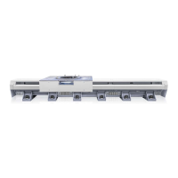
Release the holding brake by pressing the
brake release button on the carriage, which
is shown in the figure, and keeping it de-
pressed.
4
Continues on next page
Product manual - IRBT 2005 101
3HAC051130-001 Revision: F
© Copyright 2015 - 2018 ABB. All rights reserved.
2 Installation and commissioning
2.4.8 Moving the carriage manually
Continued