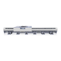
Alignment in Z direction
The figure shows the possible variation along the Z-axis.
The track should be laser aligned to within 0.2 mm from the origin per meter, along
the entire X-axis.
xx1400001473
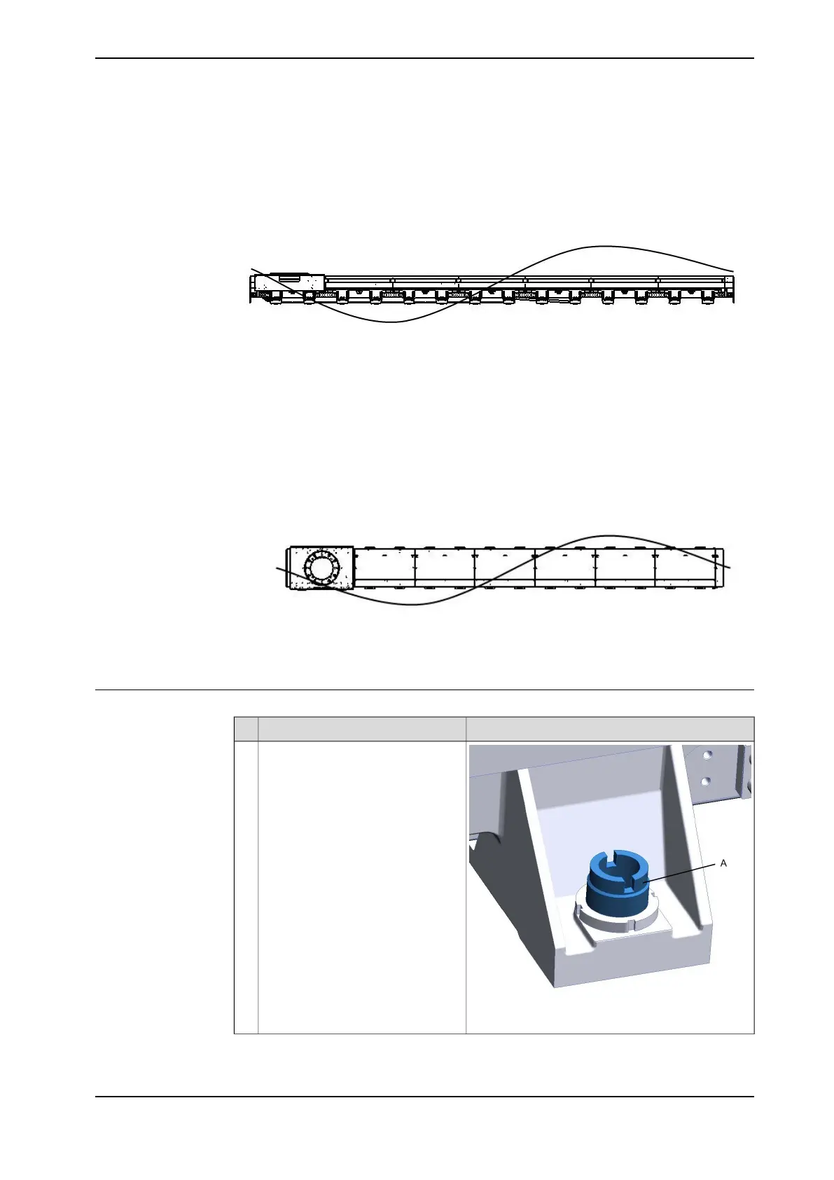
Alignment in Y direction
The figure shows the possible variation along the Y-axis.
The track should be laser aligned to within 0.5 mm from the origin per meter, along
the entire X-axis.
xx1400001474
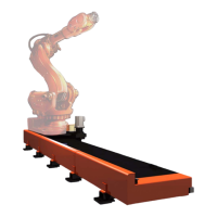
Leveling screw adjustment method
Illustration/NoteAction
xx1400000463
A Leveling screw
Screw the leveling screw (A) in or
out to raise or lower the machining
in question.
1
Continues on next page
Product manual - IRBT 2005 97
3HAC051130-001 Revision: F
© Copyright 2015 - 2018 ABB. All rights reserved.
2 Installation and commissioning
2.4.7 Geometric alignment of track motion IRBT 2005
Continued