430 Power/Electronics Replacement
Replacing the main board
2 of 26
Jun 2001
Mainframe
Agilent 6890 Gas Chromatograph Service Manual
P19 AC board control
P21 Inlet/Detector heated zones — Remove the Inlet/
Detector wiring harness connectors from the
main board sheet metal bracket.
P22 Valve box and aux heated zones
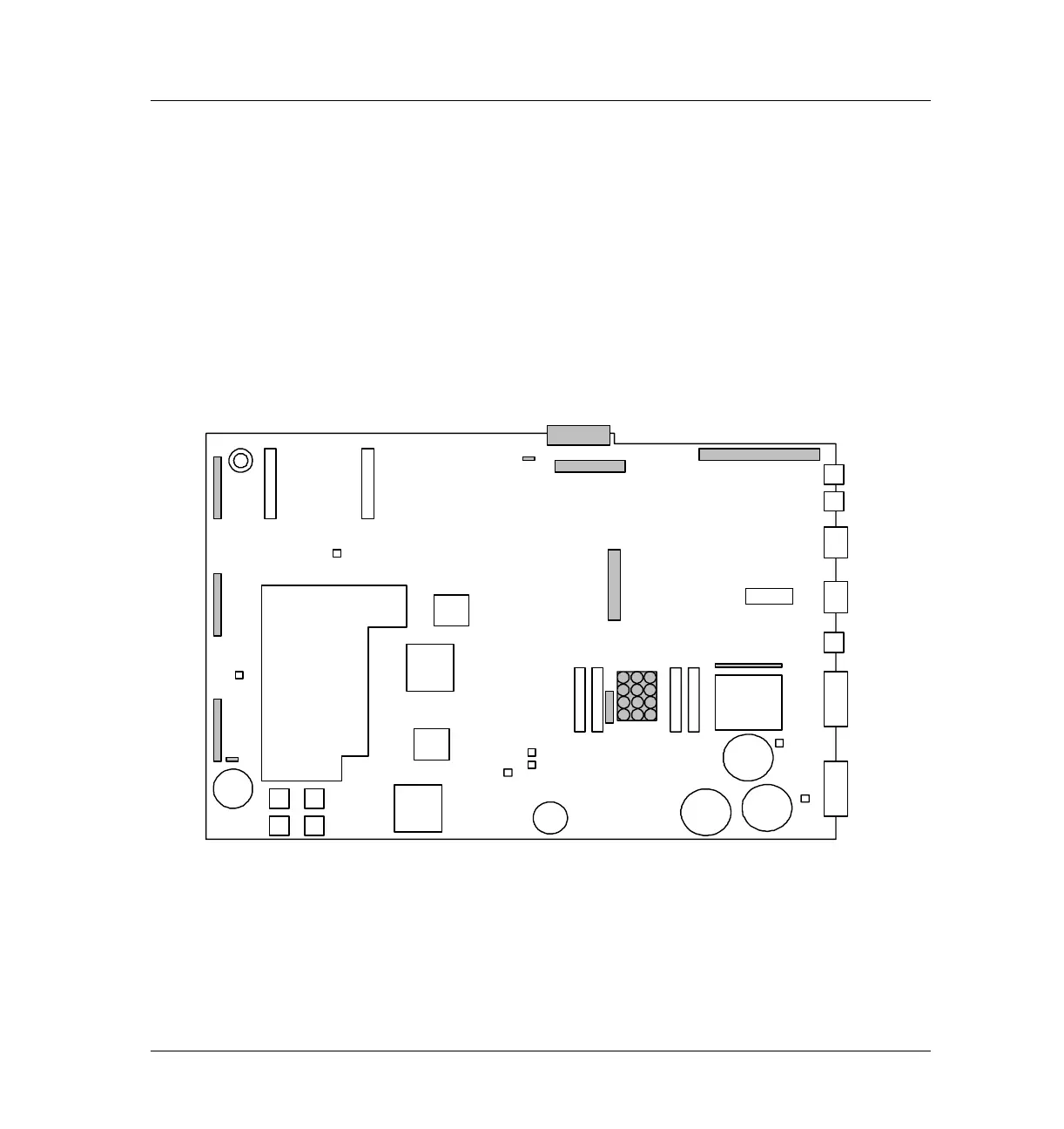
After disconnecting the EPC ribbon cable (P3) and AC Power harness
(J7), pull them back through their slots and out of the way.
Figure 430-1 Main board connectors, 6890A and 6890 Plus
Hole for
transformer
Oven Access
Cutout
Beeper
P11
P2
P12
P13
P17
P15
DSP
Gate
Array
CPU
GND
4 ROM
Sockets
3V
Lithium
battery
Gate
Array
P16
P21
P22
P3
J1
J2
JP1
JP2
J4
J6
J5
F2 F1
F4 F3
P18
+24V
–24V
+15V
–15V
+5v
Capacitor
Capacitors
cable
J8
GND
P1
J7
P19

 Loading...


