EasyManuals Logo

Agilent Technologies 6890 Series Service Manual

Agilent Technologies 6890 Series
867 pages
To Next Page IconTo Next Page
To Previous Page IconTo Previous Page
Page #434 background imageLoading...
Page #434 background image
3 of 26
Jun 2001
Mainframe
Agilent 6890 Gas Chromatograph Service Manual
Power/Electronics Replacement 430
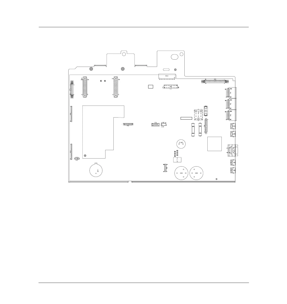
Replacing the main board
Figure 430-2 Main board connectors, 6890N
4. Unplug any cables from the connectors on the back of the instrument.
5. If any valve actuators were installed, unclip the wiring harness from each
actuator and pull the connectors out of the actuator bracket.
6. Remove the two screws securing the actuator bracket and remove the
bracket.
-24V
-15V
GND
+24V
+15V
+5V
-10V REF
GND
P2
F4 F5
P11
P12
P13
P1 P2
P21
P3
P22
P18
J7
P16
P19
P17
P4
P5
P6
J1
J2
JP1
J4
J6
P14

Table of Contents

Other manuals for Agilent Technologies 6890 Series

Questions and Answers:

Question and Answer IconNeed help?

Do you have a question about the Agilent Technologies 6890 Series and is the answer not in the manual?

Agilent Technologies 6890 Series Specifications

General IconGeneral
BrandAgilent Technologies
Model6890 Series
CategoryLaboratory Equipment
LanguageEnglish

Related product manuals