Agilent 7820 GC Service
163
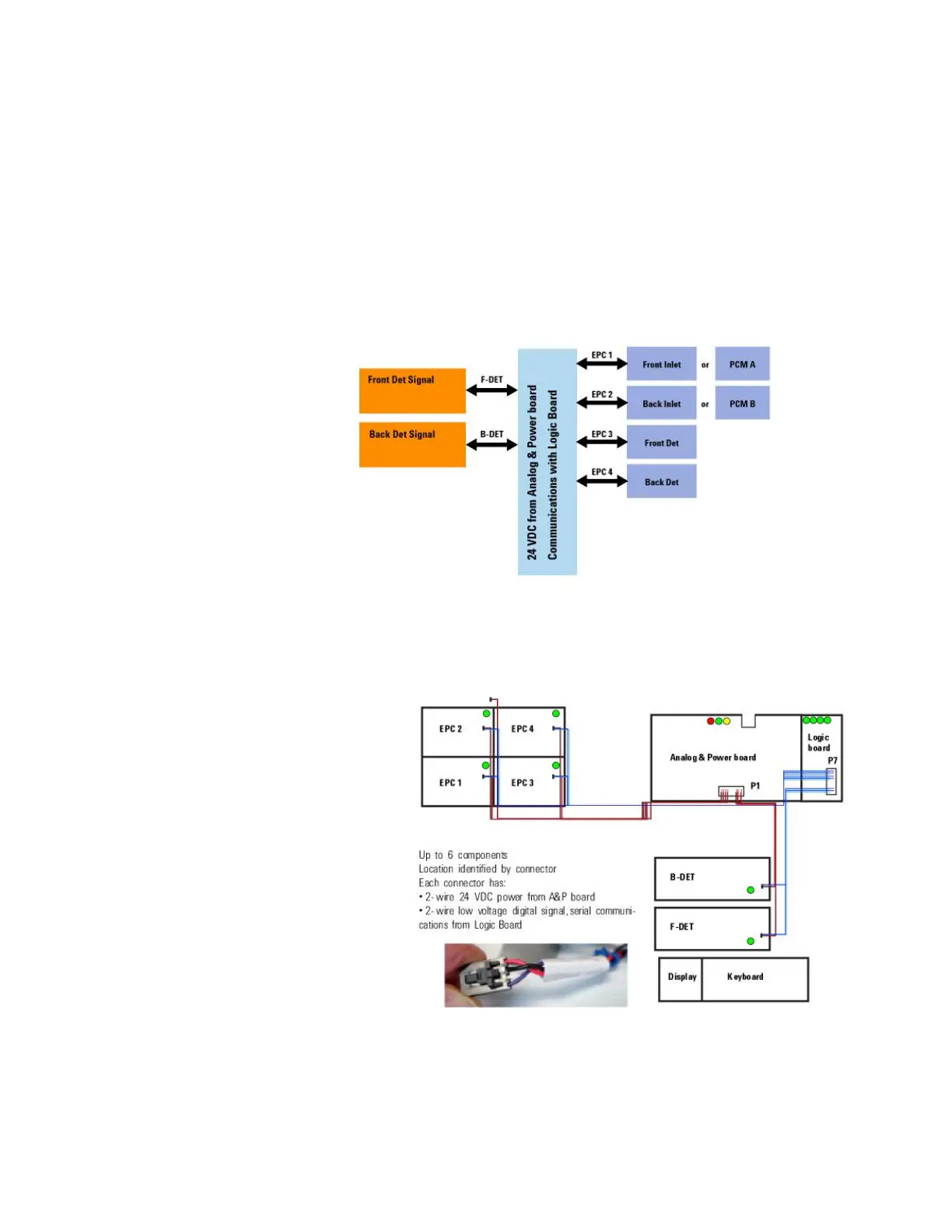
GC modules and the communications buss
This GC provides a flexible architecture. Along with the flexibility,
the configuration of the GC can be more complex. The flexible
architecture is represented in this schematic. Above each arrow
is a label that represents an address on a communications buss.
The 4-wire communications buss is the nervous system of the
GC. It connects to up to 4 EPC modules and up to 2 detector
signal boards. On each of the 6 connectors, there is a label to
help identify what can be plugged in.
The red and black wires on the buss provide power to the
module. The black wire is ground. The red wire is switched,
unregulated +24 VDC. All of these wires plug into the Analog and
Power Board. The white and colored wires provide serial

 Loading...


