202
Agilent 7820 GC Service
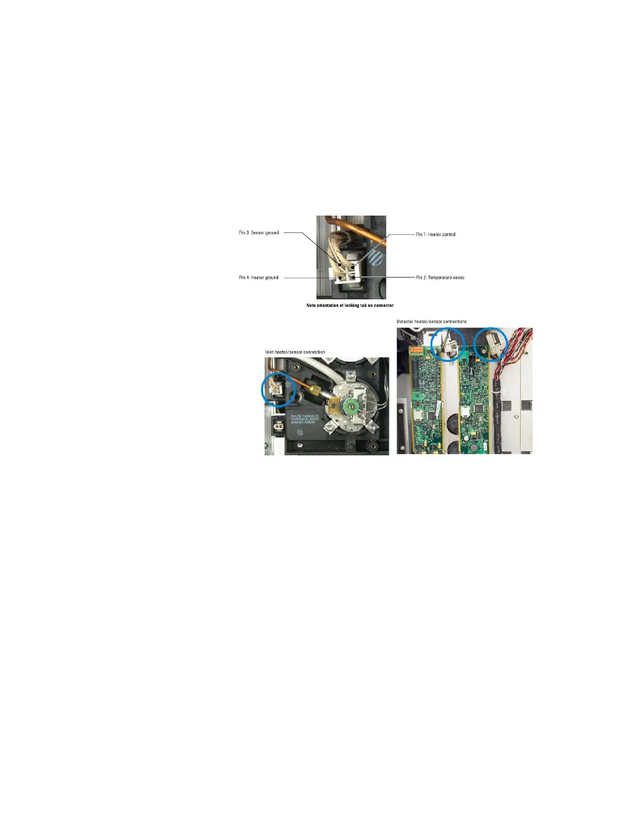
heater/sensor connector to be tested.
For inlets, remove the inlet cover and GC left side panel
For detectors, remove the electronics cover and GC right
side panel
Remove the connector from the GC chassis.
Use an Ohmmeter to measure the resistance across the
connector pins of the heater/sensor cable.
For heated zones the PRT is connected to the white wires
on pins 2 and 3 of the connector.
With the heater/sensor connector removed from the GC,
there should be no connection to ground on any of the
four pins. A reading of ~0 indicates a possible shorted
sensor or heater.
Compare the results against the tables below.

 Loading...


