210
Agilent 7820 GC Service
Components can be damaged by static electricity:
be sure to wear an ESD strap grounded to the GC
chassis while performing this procedure.
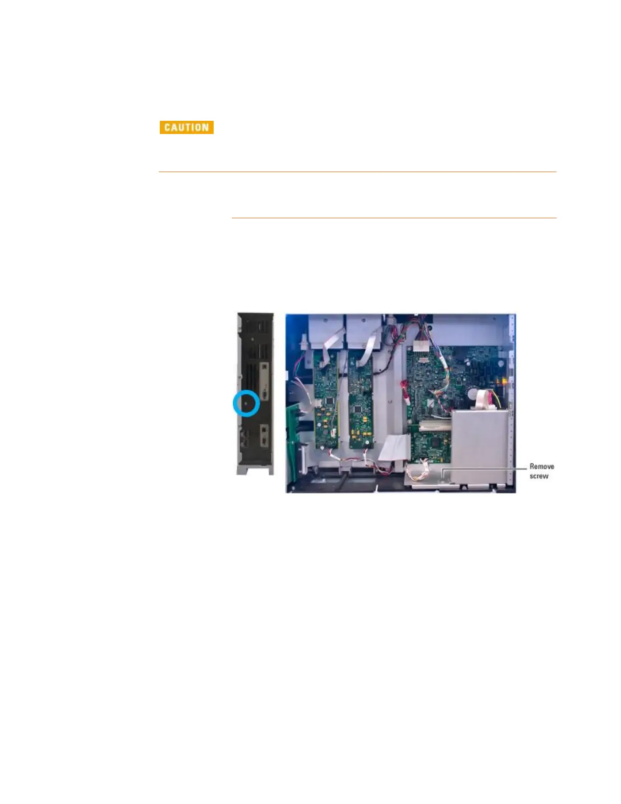
Remove the right side panel.
Remove 1 T-20 screw holding the assembly to the back of the
electronics carrier.
Remove 1 screw that secures the ALS board assembly to the
mainframe.
Slide out the ALS assembly.
Pinch and pull the 2-wire power connection at the bottom of the
assembly and set the assembly aside.
Carefully pinch and disconnect the flex cable from J8 on the
Analog & Power board.
 Loading...


