222
Agilent 7820 GC Service
Slide the board slightly outward and to its left to release it from
the GC.
Installation of the new board is essentially the reverse of removal
steps with the following considerations:
Make sure the long grounding screw is returned to its
proper location
Be careful in returning all screws to their proper locations
in that you avoid accidental contact with / damage to
nearby board components
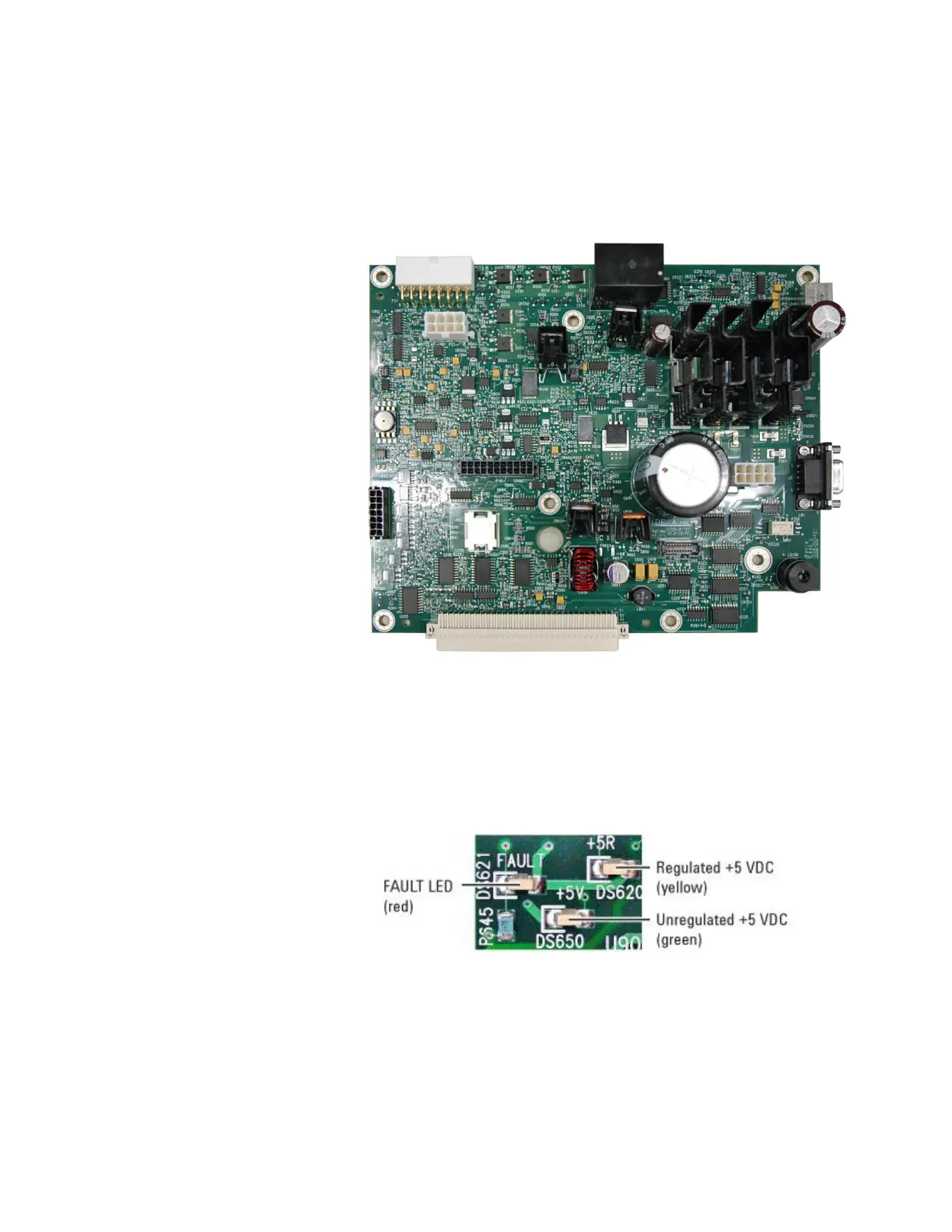
The LEDs for the Analog and power board are located in the
middle on the right next to the remote connector ( 286) . When
power is restored, yellow and green LEDs should be lit (on)
indicating, respectively, that regulated and unregulated +5 VDC
supplies are functional. The red LED is lit only under FAULT
conditions.

 Loading...


