Chapter 7: Building the Trunk with the Default SFP+ S1 and S2 10Gbps Stacking Ports
134
To power on the stack for the first time and control the assignment of the
ID numbers, perform the following procedure:
1. If you have not already cabled ports, do so now. For background
information, refer to “Stack Trunks” on page 63, For cabling
instructions, refer to Chapter 9, “Cabling Copper Ports” on page 174.
2. Power on the switch you want assigned ID number 1. Connect its
power cord to the AC connector on the back panel and to an
appropriate power source. Refer to “Powering on a Switch” on
page 146.
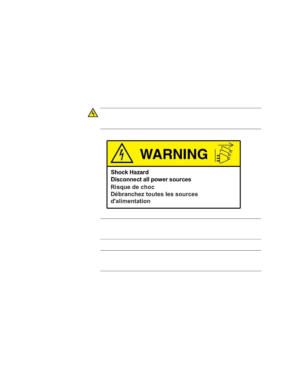
Warning
Power cord is used as a disconnection device. To de-energize
equipment, disconnect the power cord. E3
Note
Pluggable Equipment. The socket outlet shall be installed near the
equipment and shall be easily accessible. E5
Note
Refer to “Power Specifications” on page 195 for the power
specifications of the switches.
3. Wait one minute for the switch to start the AlliedWare Plus software.
The switch displays the number 1 on its ID LED and is now the master
switch.
4. Power on the switch to be assigned ID number 2.
5. Wait two minutes for the new switch to join the stack as a member.

 Loading...


