4. Programming
113
ML-2050A/2051A/2150A
Chapter 4 Laser Welding by External Input/ Output Signals (EXTERNAL CONTROL)
Introduction Part
Installation and
Preparation Part
Operating Part Maintenance Part Appendixes
4
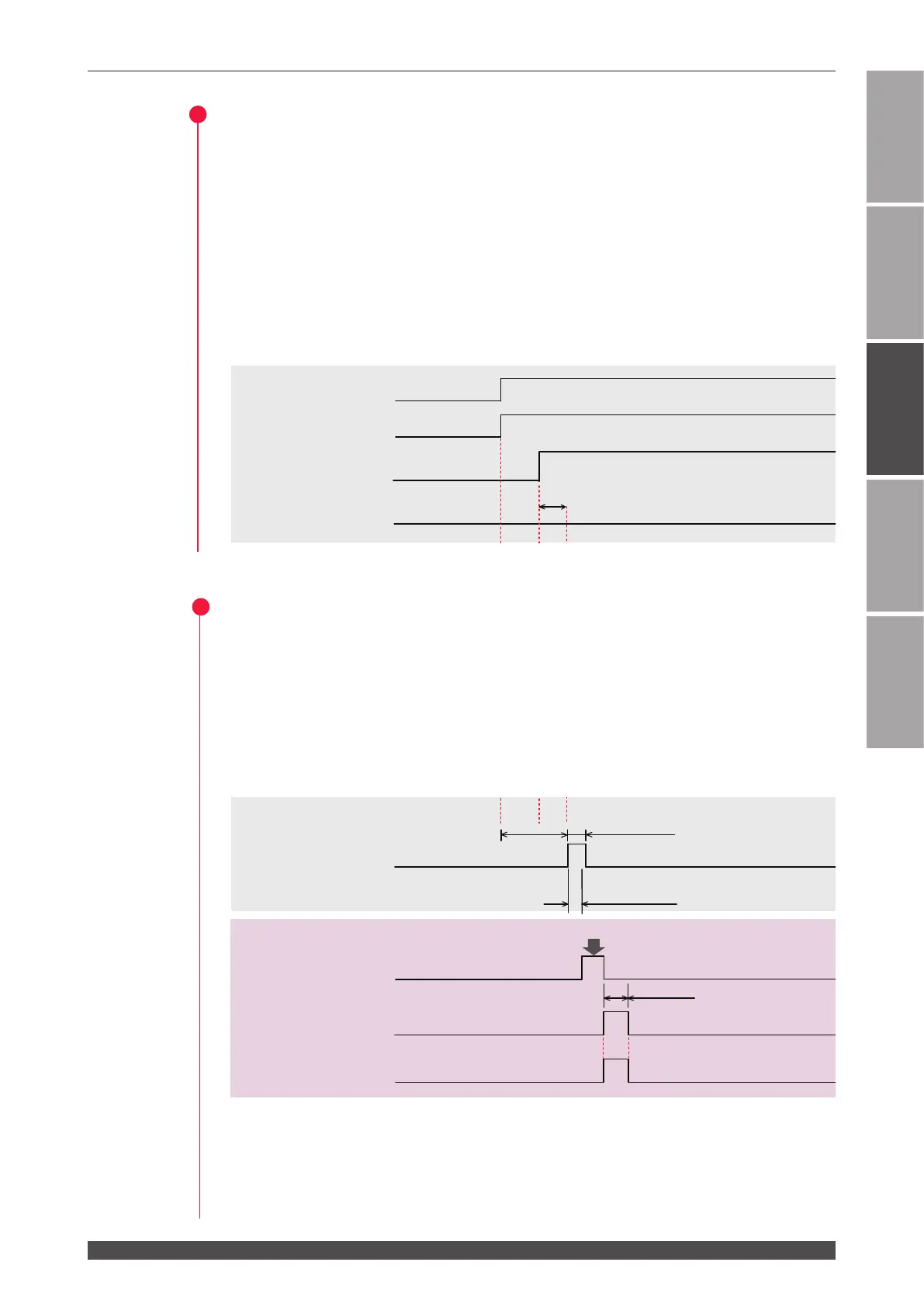
Setting Output Schedules (SCH.#01)
(1) Set the SCHEDULE number by combining pin No.29 to pin No.33 of the EXT.I/O
(1) connector. In this example, pin No.29 of the EXT.I/O (1) connector is put in a
closed circuit for 16 ms or more to set SCH.#01.
⇒
Refer to "SCHEDULE Number Selection" on page 99.
⇒
At delivery, the signal acceptance time (time from a signal input till establishment
of schedules) of welding schedules is set to 16 ms. Set the close circuit time
referring to this value.For the signal acceptance time, 1.0 ms, 4.0 ms, 8.0 ms,
or 16.0 ms can be selected by setting the DIP switch on the CPU board. For
details, refer to Chapter 2, "3. Changing the Acceptance Time for Laser Start
Signal/Schedule Signal" on page 83.
5
Outputting Laser Light
(1) Put pin No.20 (Laser Start) of the EXT.I/O (1) connector in a closed circuit.
Laser light is output simultaneously from Beam 1 and Beam 2.
Pin No.4 (End output) of the EXT.I/O (1) connector is put in a closed circuit for 50
ms and a signal is returned from the laser. Pin No.5 (Monitor normal output) or
pin No.6 (Monitor abnormal output) of the EXT.I/O (1) connector is put in a closed
circuit and a signal is returned from the laser.
⇒
Put the laser start pin in a closed circuit at least in 150 ms after inputting the
beam selection signal or in more than the time set by the DIP switch after setting
welding schedules.
⇒
At delivery, the laser start acceptance time (time from a signal input till an actual
output of laser light) is set to 16 ms. For the laser start acceptance time, 1.0 ms,
(Laser light)
End output
48 sec. max.
Over the time set by the DIP switch
150ms or more
50ms
Control switching
input
Ready output
SCHEDULE 1
input
SCHEDULE 2
input
BEAM SELECT 1
input
BEAM SELECT 2
input
Laser start input
ON
OFF
ON
OFF
ON
OFF
ON
OFF
ON
OFF
ON
OFF
ON
OFF
ON
OFF
ON
OFF
ON
OFF
ON
OFF
Completion of charging
HV-ON
OFF input
External input
acceptable output
Output
(Laser light)
End output
50ms
SCHEDULE 1
input
SCHEDULE 2
input
Laser start input
ON
OFF
ON
OFF
ON
OFF
ON
OFF
ON
OFF
ON
OFF
Output
Monitor normal
output
Monitor normal
output
The time set by the DIP switch
Over the time set
by the DIP switch
Over the time set by
the DIP switch
Over the time set by
the DIP switch
(Laser light)
End output
48 sec. max.
Over the time set by the DIP switch
150ms or more
50ms
Control switching
input
Ready output
SCHEDULE 1
input
SCHEDULE 2
BEAM SELECT 1
input
BEAM SELECT 2
input
Laser start input
ON
OFF
ON
OFF
ON
OFF
ON
OFF
ON
OFF
ON
OFF
ON
OFF
ON
OFF
ON
OFF
ON
OFF
ON
OFF
Completion of charging
HV-ON
OFF input
External input
acceptable output
Output
(Laser light)
End output
50ms
SCHEDULE 1
input
SCHEDULE 2
input
Laser start input
ON
OFF
ON
OFF
ON
OFF
ON
OFF
ON
OFF
ON
OFF
Output
Monitor normal
output
Monitor normal
output
The time set by the DIP switch
Over the time set
by the DIP switch
Over the time set by
the DIP switch
Over the time set by
the DIP switch
↓
↓↓
↓
↓↓
 Loading...


