30
ML-2050A/2051A/2150A
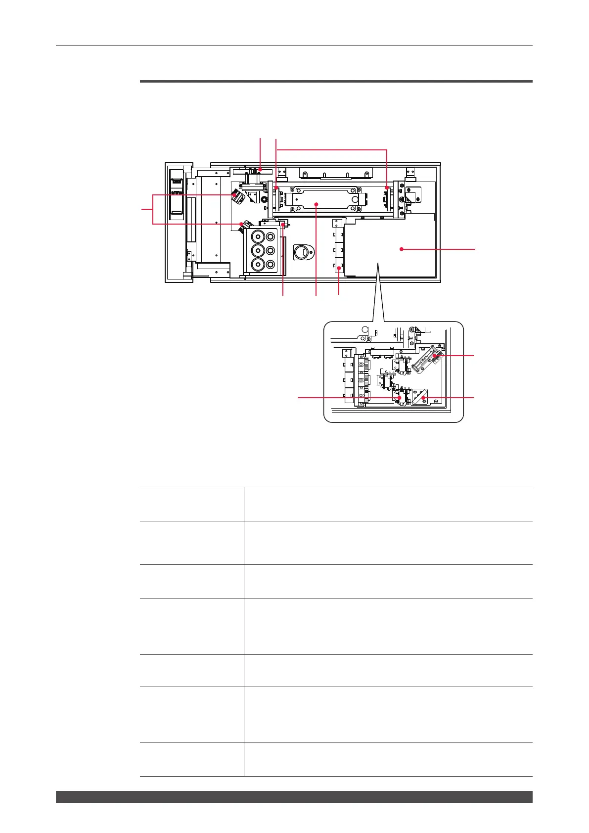
2. Name and Function of Each Section on the Top Side
Laser Oscillator Section
In the following, the laser oscillator section that is provided inside the top
cover is explained.
Function of Each Section on the Laser Oscillator
(1) Power Monitor
Unit
Detects the YAG laser beam and measures its power.
(2) Resonator Mirror
Holder
Holds the resonator mirror. Light excited in the Laser Chamber is
amplified between the two resonator mirrors and output as a laser
beam.
(3) Guide Beam
Reecting Mirror
Adjusts the guide beam (visible laser beam) so that this beam passes
down the center of the YAG laser beam’s optical path.
(4) Guide Light
Oscillator
This oscillator outputs guide light (red visible laser).
Because YAG laser for welding is invisible, red guide light is used
to perform oscillation adjustment, incident adjustment, welding point
positioning, etc.
(5) Laser Chamber
Contains the ashlamp and the YAG rod. The ashlamp lights up to
excite the YAG rod and emit laser beam.
(6) Laser Beam Input
Unit (Up to 3
optional deliveries)
Connect the optical fiber to this unit. The Laser Beam Input Unit
projects a laser beam from the laser chamber into the optical fiber.
Depending on the specification, 1 to 3 laser beam input units are
installed.
(7) Branch Unit
Cover
Do not remove this cover except when installing and removing the
optical ber.
(7)
(1) (2)
(4) (5) (6)
(3)
(8)
(9) (10)
Inside of the branch section