112
ML-2050A/2051A/2150A
4. Programming
4. Programming
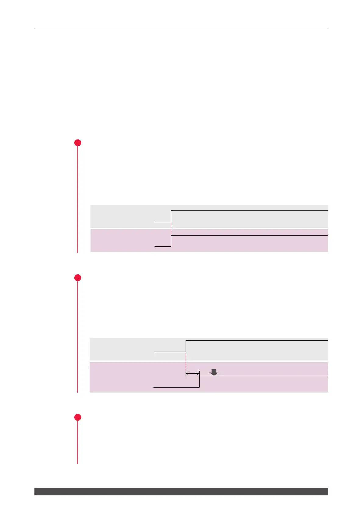
This section explains the precautions for programming laser welding by
external input/output signals (EXTERNAL CONTROL).
The timing chart of the appendix shows the input signal length and input waiting time
required to correctly operate the laser. Perform actual programming referring to this
timing chart.
In the following, a control ow is explained by taking the case where "Schedule 1" is
rst specied and then "Schedule 2" is specied to perform a single laser light output
by 2-powersharing from BEAM1 and BEAM2, as an example.
1
Switching the Control Method
(1) Put pin No.23 (control switching) of the EXT.I/O (1) connector in a closed circuit.
Pin No.8 of the EXT.I/O (1) connector is put in a closed circuit and the signal
(external input acceptable) is returned from the laser.
⇒
Press the MENU key on the control panel to display the STATUS screen. Then,
you can conrm that "EXTERNAL CONTROL" is selected as the control method.
2
Turning ON the High Voltage
(1) Put the section between pin No.18 of the EXT.I/O (1) connector and COM to turn
ON the high voltage.
The capacitor can be charged in 48 sec. max. At completion of charging, pin
No.1 of the EXT.I/O (1) connector is put in a closed circuit and the signal (Ready)
is returned from the laser.
3
Selecting a Beam (Setting the Branch Shutter)
(1) Put the section between the pin corresponding to the beam and COM in a closed
circuit. In this example, the section between pin No.25 and pin No.26 of the EXT.
I/O (1) connector is put in a closed circuit to select Beam 1 and Beam 2.
The branch shutter is opened and the corresponding SHUTTER lamp comes on.
48 sec. max.
Over the time set by the DIP switch
150ms or more
50ms
Control switching
input
Ready output
SCHEDULE 1
input
SCHEDULE 2
input
BEAM SELECT 1
input
BEAM SELECT 2
input
Laser start input
ON
OFF
ON
OFF
ON
OFF
ON
OFF
ON
OFF
ON
OFF
ON
OFF
ON
OFF
ON
OFF
ON
OFF
ON
OFF
Completion of charging
HV-ON
OFF input
External input
acceptable output
Output
(Laser light)
End output
50ms
SCHEDULE 1
input
SCHEDULE 2
input
Laser start input
ON
OFF
ON
OFF
ON
OFF
ON
OFF
ON
OFF
ON
OFF
Output
Monitor normal
output
Monitor normal
output
The time set by the DIP switch
Over the time set
by the DIP switch
Over the time set by
the DIP switch
Over the time set by
the DIP switch
(Laser light)
End output
48 sec. max.
Over the time set by the DIP switch
150ms or more
50ms
Control switching
input
Ready output
SCHEDULE 1
input
SCHEDULE 2
input
BEAM SELECT 1
input
BEAM SELECT 2
input
Laser start input
ON
OFF
ON
OFF
ON
OFF
ON
OFF
ON
OFF
ON
OFF
ON
OFF
ON
OFF
ON
OFF
ON
OFF
ON
OFF
Completion of charging
HV-ON
OFF input
External input
acceptable output
Output
(Laser light)
End output
50ms
SCHEDULE 1
input
SCHEDULE 2
input
Laser start input
ON
OFF
ON
OFF
ON
OFF
ON
OFF
ON
OFF
ON
OFF
Output
Monitor normal
output
Monitor normal
output
The time set by the DIP switch
Over the time set
by the DIP switch
Over the time set by
the DIP switch
Over the time set by
the DIP switch