28
ML-2050A/2051A/2150A
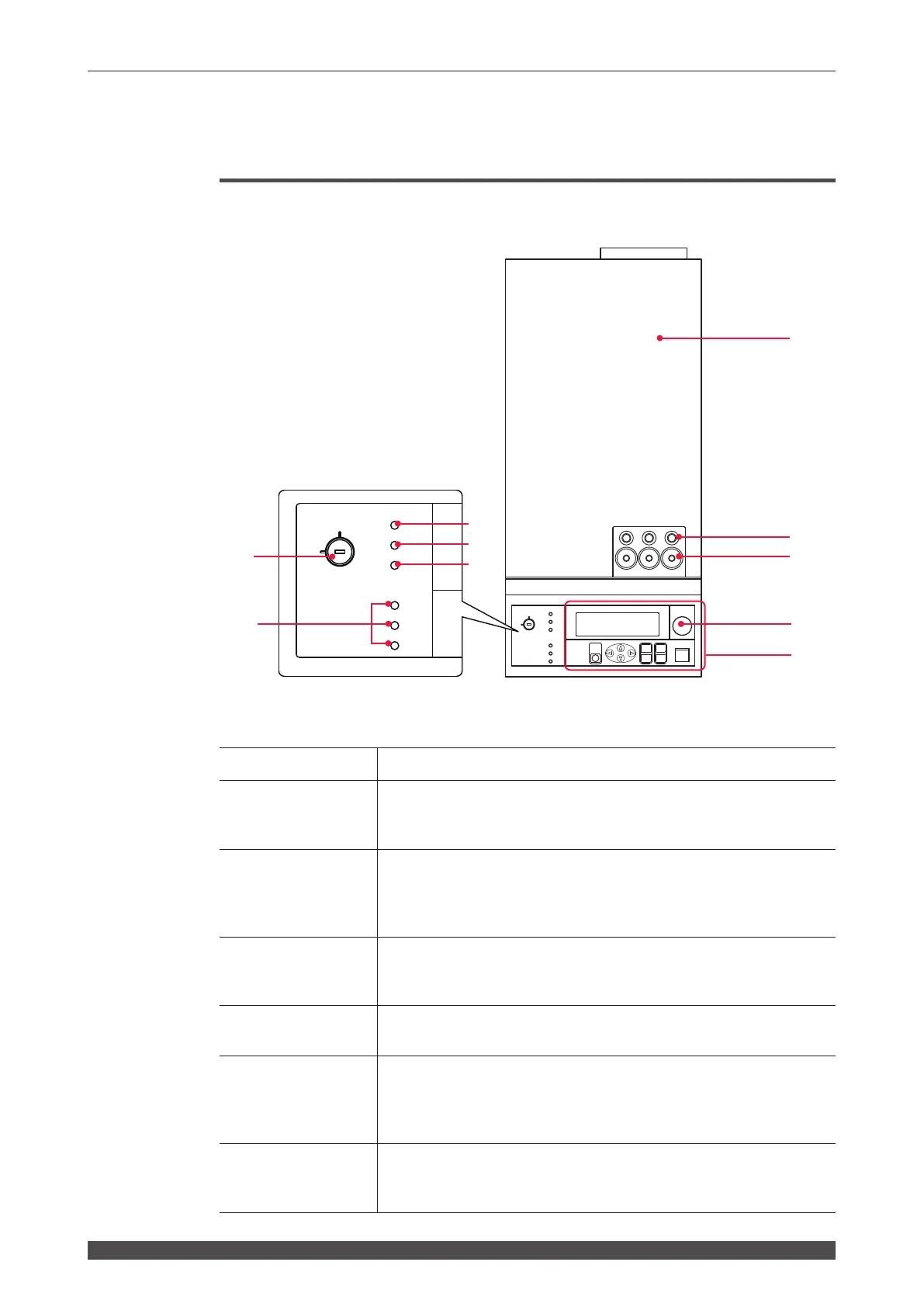
2. Name and Function of Each Section on the Top Side
2. Name and Function of Each Section on the Top Side
Top Cover Section
This section explains each section of the top cover of the main unit.
Function of Each Section on the Top Cover
(1) Head Cover
Cover for the laser oscillator.
(2) Cable Inlet
This is a hole to pass the cable for detection of optical ber mounting/
breaking (option). The numbers of the output units connected to the
cable inlet are 1, 2, and 3 in sequence from the left in the gure.
(3) Optical Fiber
Inlets
Make the required number (number of deliveries) of holes in the rubber
cap.
Pass the optical fibers through these holes and connect them to the
laser beam input units. These inlets are on the top and rear side.
(4) EMERGENCY
STOP Button
This is an emergency stop button. The power supply of the laser is cut
o with this button pressed. When the pressed button is turned toward
RESET (clockwise), the button is reset to the initial state.
(5) Control Panel
This panel is used to set welding schedules and operate the laser.
Setting items and set values are displayed on the liquid crystal display.
(6) CONTROL
Keyswitch
When the CONTROL keyswitch is turned ON with the MAIN POWER
switch ON, this keyswitch is operable. When the laser is not used, turn
OFF the CONTROL keyswitch and then pull out the key. The laser
safety supervisor should take charge of the keyswitch.
(7) POWER Lamp
When the MAIN POWER switch is turned ON, the POWER lamp
comes on so that the operator can check that the power supply has
been turned ON.
ON
OFF
CURSOR
RESET
MENU
OFF
(-)
(+)
ENTER
TROUBLE
ON
Y
E
G
R
M
E
E
T
P
O
C
N
S
SHUTTER 1
SHUTTER 2
READY
SHUTTER 3
CONTROL
HIGH VOLTAGE
POWER
START/STOP
LASER
EMISSION
POWER
READY
ON
OFF
SHUTTER 1
SHUTTER 2
SHUTTER 3
CONTROL
HIGH VOLTAGE
(1)
1 2 3
(2)
(3)
(5)
(4)
(6)
(7)
(8)
(9)
(10)