3. Connecting the Optical Fiber
43
ML-2050A/2051A/2150A
Chapter 2 Connections and Preparations of Each Section
Introduction Part
Installation and
Preparation Part
Operating Part Maintenance Part Appendixes
3. Connecting the Optical Fiber
This section explains the method of connecting the optical ber.
In this laser, a high-precision type optical ber is adopted. Once the incident optical
axis is adjusted, this optical axis does not need to be adjusted again after the ber is
mounted.
WARNING
■ Be sure to receive education for this work from our engineer.
■ Before starting work, be sure to turn OFF the power supply.
Before Connection
Before making a connection, check the end face of the optical ber. If it is stained or
dust is attached, blow it o by air blow or wipe it out with lens cleaning paper.
For how to clean the optical fiber, refer to the Maintenance Part, Chapter 1, "3.
Maintenance of the Laser Oscillator Section" on page 160.
⇒
For a check for stain, use the optional end face checker.
⇒
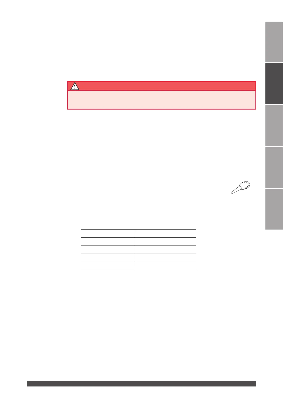
Use such an air blow dedicated to cameras as shown at right. If rubber is
deteriorated, dust may enter the optical ber. Use a clean air blow.
Precautions during Operation
⇒
During operation, take care not to give shocks to the optical ber or bend it below
the minimum bending radius (in the following table).
Minimum bending radius of the optical ber
Core diameter Minimum bending radius
φ 0.2, 0.3, 0.4mm 100mm
φ 0.6mm 150mm
φ 0.8mm 200mm
φ 1.0mm 250mm
⇒
Do not tighten the ring of ber plug too rmly; otherwise the incident laser beam
may be dislocated. Tighten the ring by hand without using a tool.