44
ML-2050A/2051A/2150A
3. Connecting the Optical Fiber
Standard Values of Maximum Incident Laser Energy and Power of the
Optical Fiber
The following table shows the standard values of maximum laser energy and power
that can be input into the optical ber. Take care not to exceed these values when
using the optical ber.
For single-delivery or timesharing
The value becomes 1/2 at 2-powersharing and 1/3 at 3-powersharing.
Core dia.
Model
ML-2050A ML-2051A ML-2150A
SI φ 0.2mm -
7J, 7W
-
SI φ 0.3mm
15J, 15W
SI φ 0.4, 0.6, 0.8, 1.0mm 25J, 25W
⇒
Use an optical ber of φ 0.4 mm core diameter or larger for ML-2150A.
⇒
Use the SI optical ber. The GI optical ber cannot be used.
Item required
Phillips screwdriver and air blow
1
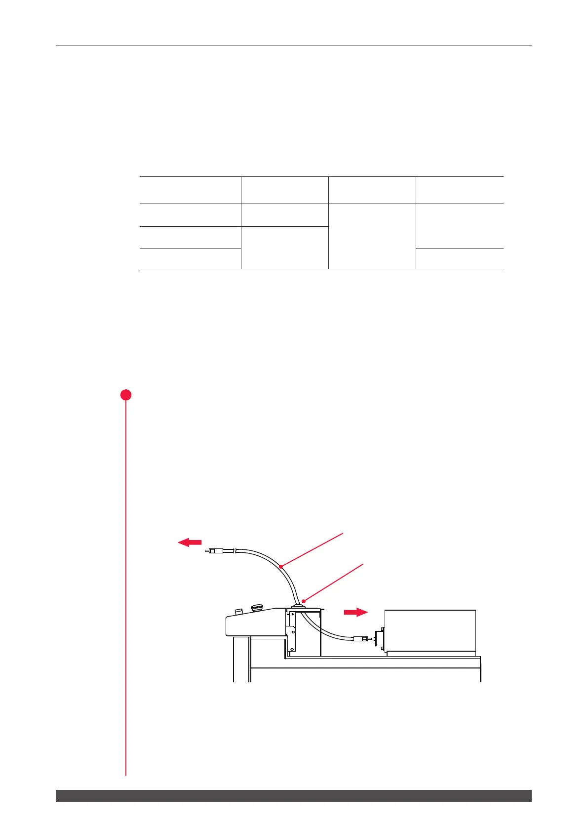
Connecting to Laser Beam Input Unit
(1) Remove the head cover.
(2) Pass the optical fiber with its cap attached into the Laser through one of the
optical ber inlets located on the Laser top and at its rear.
(3) Remove the cap from the end of the passed ber and blow o any dust using an
air blow.
(4) Connect the fiber to the laser beam input unit, with the key of the fiber plug
aligned with the groove of the unit.
To output unit
To input unit
Optical ber
Optical ber inlet