3. Operating Procedure
89
ML-2050A/2051A/2150A
Chapter 3 Laser Welding by Control Panel (PANEL CONTROL)
Introduction Part
Installation and
Preparation Part
Operating Part Maintenance Part Appendixes
3. Operating Procedure
This section explains the operating procedure for laser welding to be controlled
from the control panel.
⇒
For the details of welding schedule settings, refer to Chapter 2, "1. Setting
Welding Schedules" on page 53. For connector functions, refer to Chapter 4, "3.
Connector Functions" on page 97.
⇒
Before turning on the power supply, put pin No.23 (control switching) of the EXT.
I/O (1) connector to an open circuit to invalidate external input signals. As a
result, the control by external input signals (EXTERNAL CONTROL) is invalidated
and "PANEL CONTROL" is displayed in "-STATUS" on the STATUS screen.
1
Starting the Laser
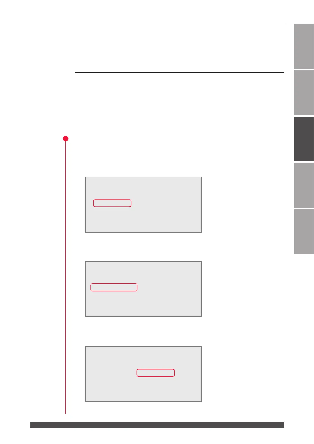
(1) Turn ON the MAIN POWER switch at the front of the main unit.
The power supply is turned ON and the POWER lamp comes on. Then, the
SELF-CHECK > screen appears.
The laser checks the opening/closing status of branch shutters, memory (sum
check and data range), and charge trouble automatically. If no trouble is found,
the KEY-SWITCH ON > screen appears.
(2) Turn ON the CONTROL keyswitch.
The laser is put to an operable status and the COOLER ON > screen appears.
WATER
28˚C
AUTO-START
SELF-CHECK >
WATER
28˚C
AUTO-START
KEY-SWITCH ON >
WATER
28˚C
AUTO-START < WAIT!! >
KEY-SWITCH ON > COOLER ON >
DEIONIZE 9.99MΩcm (READY)
WATER TEMPERATURE (NORMAL)
LASER POWER MONITOR (NOT READY)